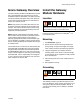
Instructions-Parts Gateway Network Communication Kits 312785C EN Installation and program setup instructions for use with ProMix® 2KS Electronic Proportioners. For professional use only. Not approved for use in European explosive atmosphere locations. See page 3 for kit information. Important Safety Instructions Read all warnings and instructions in this manual and in your proportioning system manual. Save these instructions.
Contents Graco Gateway Kits . . . . . . . . . . . . . . . . . . . . . . . . . 3 Related Manuals . . . . . . . . . . . . . . . . . . . . . . . . . . . 3 Warnings . . . . . . . . . . . . . . . . . . . . . . . . . . . . . . . . . 4 Graco Gateway Overview . . . . . . . . . . . . . . . . . . . . 5 Install the Gateway Module Hardware . . . . . . . . . . 5 Location . . . . . . . . . . . . . . . . . . . . . . . . . . . . . . . 5 Mounting . . . . . . . . . . . . . . . . . . . . . . . . . . . . . . . 5 Grounding . .
Graco Gateway Kits Graco Gateway Kits Related Manuals 15V331 Gateway Ethernet Kit Component Manuals in English Allows communication between ProMix 2KS and a PLC over an ethernet. Enables process equipment to read variables while operating, as well as control the ProMix 2KS and change setup. It does not provide access to job and alarm logs. 15V963 Gateway DeviceNet Kit Allows communication between ProMix 2KS and a PLC, using DeviceNet process control.
Warnings Warnings The following warnings are for the setup, use, grounding, maintenance, and repair of this equipment. The exclamation point symbol alerts you to a general warning and the hazard symbols refer to procedure-specific risks. When these symbols appear in the body of this manual, refer back to these Warnings. Product-specific hazard symbols and warnings not covered in this section may appear throughout the body of this manual where applicable.
Graco Gateway Overview Graco Gateway Overview The Graco Gateway enables the ProMix 2KS to network with a programmable logic controller (PLC). Kits are available for Ethernet, DeviceNet, or Profibus protocols. The Graco Gateway will support many other protocols; contact Graco Technical Assistance for information to support your desired protocol. NOTE: Only persons very familiar with their PLC communication architecture should use this hardware and software.
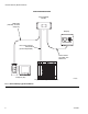
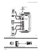
Install the Gateway Module Hardware NON-HAZARDOUS AREA Graco Gateway Module USB Cable (included), for initial setup only EasyKey PLC Communication Wire/Cable (protocol dependent) 2-wire twisted pair cable, with shield wire Computer (PC) TI13939a Programmable Logic Controller (PLC) FIG.
Install the Gateway Module Hardware Connect the Module to the EasyKey FIG. 1 is only a guide showing installation of the Graco Gateway in a ProMix 2KS System; it is not a complete system design, Contact your Graco distributor for assistance in designing a system to suit your particular needs. 1. Shut off ProMix 2KS power (0 position). FIG. 2. Also shut off power at main circuit breaker. 0 = OFF TI12657a FIG. 2: Power Off 2.
Install the Gateway Module Hardware EasyKey (Bottom View) TI12638a 2-wire twisted pair cable, with shield wire (to Gateway Module) Gateway Module USB Port TI12930a Communication Wire/Cable (to PLC). This connection is protocol dependent. 2-wire twisted pair cable, with shield wire (to EasyKey). See Wiring Diagrams on page 41 for pin connections. FIG.
Pin 6 Pin 1 Install the Gateway Module Hardware Common 24 Vdc +/- 10% N/C Power Connector RS232/PG Pin 1 Pin 8 USB/PG Expansion Port Pin 6 Pin 1 COMMS Yellow LED Green/ Amber LED COMMS ETHERNET (NIC) TI13974a FIG. 4: Graco Gateway Port Pin Outs TI13972a FIG.
Install the Gateway Module Hardware RS232/PG OR USB/PG OR ETHERNET TI13969a Green/Amber LED Yellow LED FIG. 6: Programming Ports RS232/PG OR TI13970a FIG. 7: RS232/PG Communication Ports RS232 TI13971a FIG.
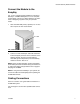
Install the Gateway Module Hardware ETHERNET Green/Amber LED Yellow LED Standard Ethernet Cable TI13973a FIG. 9: Ethernet Connection Mount the Control on DIN Rail Install CompactFlash® Card The Gateway control mounts on a DIN rail. Tilt the control and push down onto the DIN rail, then push in. See FIG. 10. A minimum clearance of 1 in. (25 mm) above and below the control is required to ensure adequate ventilation. The CompactFlash socket accepts either Type I or Type II cards.
Install the GracoConfig Software Install the GracoConfig Software GracoConfig software provides access to the Graco Gateway module hardware. The CD provided contains the GracoConfig software (GracoConfigXXX.exe, where the XXX represents the version control number). It also includes a preconfigured database which is essentially a setup file for the Gateway. The database file has a .gg2 extension.
Install the GracoConfig Software Load the Software 1. Connect the USB cable (23, supplied) between the USB port on the Gateway module and a USB port on your PC. See FIG. 12. 3. FIG. 14 will appear. Insert the CD in your PC’s CDROM drive. Select “Install the software from a list or specific location”, then click Next. The program location is C:\Program Files\Graco\GracoConfig\Device. NOTE: The name of the driver may be different. Just accept the name and proceed by following the instructions on the screen.
Install the GracoConfig Software Download the Preconfigured Database to the Gateway Module 2. Using the Link pulldown menu, select Options to open the Link Options window. Check that the Communications Port is set to USB, and click OK. Graco supplies a preconfigured database as a setup file for the Gateway, containing parameters which communicate between the Gateway and the ProMix 2KS. The file name has a .gg2 extension. GracoConfig files are downloaded to the Gateway module using the Link menu.
Graco Gateway Network Communications Configuration Graco Gateway Network Communications Configuration Startup To run GracoConfig, select the icon GracoConfig Main Page from the Graco folder on the Programs section of your Start Menu. The main page will appear, showing the Communications button.
Graco Gateway Network Communications Configuration Setup the Database 1. Double-click on the Communications button to open the preconfigured database (.gg2). The file is already setup for ProMix 2KS. See FIG. 18. FIG. 18: Preconfigured Database 2. See FIG. 19. Highlight Protocol 1. Click the Edit button on the right side of the window to open the Driver Picker window. Choose a protocol from the lists provided, in this example Modbus and TCP/IP Slave. The system will create device PLC1. FIG.
Graco Gateway Network Communications Configuration 3. See FIG. 20. Right click on device PLC1 to rename it to something meaningful for your system. FIG. 20: Rename PLC1 4. See FIG. 21. Add as many Gateway blocks as desired under each device. FIG.
Graco Gateway Network Communications Configuration Map Data 1. See FIG. 22. Select the block for data mapping. Click the Edit button next to the Start Address field on the right side of the window. The Select Address window will open. 2. Refer to Table 4 on page 30 for a Modbus map. Select the desired Modbus register address as a starting point (in this case 40002). Enter the appropriate values in the Select Address window and click OK. The desired register address will populate the Start Address field.
Graco Gateway Network Communications Configuration 3. See FIG. 23. Click the Edit button next to the Block Size field on the right side of the window. The Edit Value window will open. Enter the number of Modbus register addresses in the range from the starting address entered in step 2 to the desired ending address, inclusive. In this example, 7. The addresses must be contiguous. This means that each address must be available and addressable from the ProMix 2KS.
Graco Gateway Network Communications Configuration 4. See FIG. 24. Click OK. The range of addresses will appear under the appropriate Block on the left side of the window. NOTE: In this example, a Modbus device master communicating via TCP/IP will have direct access to Modbus registers 40002 through 40008 of the ProMix 2KS. For example, see Block 1 address line 1: Modbus address of ProMix 2KS. Modbus address (command) from TCP/IP master connected to Gateway. 5.
Modbus and I/O Data Modbus and I/O Data See Table 4 through Table 5 for Modbus register addresses and input/output data. 2. The Mix Active output should clear and Mix Ready should now be set. Reference the Discrete I/O listing of all the inputs and outputs (see page 30). Ensure these are fully understood. The same implementation used for Discrete I/O is used for the Network communication protocol. NOTE: The ProMix 2KS will automatically go into Idle mode after 2 minutes of inactivity.
Modbus and I/O Data Start Mix Mode Process NO YES Is Mix Ready bit = 1? Must be Alarm Condition or Active Recipe 61. See Alarm Processing on page 26, or Startup from Recipe 61 (see NOTE below) Set Mix bit = 1 NO NOTE: At power up the system defaults to Recipe 61, which is not a valid recipe number. Initiate a color change to Recipe 0 or a valid recipe number (1-60). Is Mix Active bit = 1? YES ProMix 2KS in Mix Mode (Complete) Mix Active = 1 while the ProMix 2KS is in Mix mode FIG. 25.
Modbus and I/O Data Mixing Mode Process Mixing Mode is desired. PLC is polling to ensure Mixing Mode is maintained. NO Is Mix Active bit = 1? YES Mixing Process active Check Alarm Condition: is Alarm_ General bit = 1? NO 2KS is in Standby. Go to Start Mix Process, page 21. YES Go to Alarm Processing, page 26 FIG. 26.
Modbus and I/O Data Start NO Is Mix Ready bit = 1? Must be Alarm Condition or Active Recipe 61. See Alarm Processing on page 26, or Startup from Recipe 61 (see NOTE below). YES Set Purge bit = 1? NO (Wait for Mix Ready) Is Mix Ready bit = 1? NO YES NOTE: At power up the system defaults to Recipe 61, which is not a valid recipe number. Initiate a color change to Recipe 0 or a valid recipe number (1-60).
Modbus and I/O Data Color Change Process (basic) Do nothing. Spraying at desired recipe. YES Is Active Recipe = to desired recipe? (Register 40005). NO Load ccNewRecipe (Register 40046) with recipe number to Color Change to (0 through 60 is valid). Ensure ColorChange bit is seen by ProMix 2KS Is Purge_CC_Active bit = 1? NO YES NO Set ColorChange (CC) bit = 1. Clear ColorChange (CC) bit (momentary input). CC process started.
Modbus and I/O Data Alarm Processing See FIG. 29, Table 1, Table 2, and Table 3. Alarm Processing An Alarm Condition has been found previously. Alarm_General = 1. NO Check if Potlife Alarm: is Alarm_ Potlife bit = 1? Two options: Determine the exact alarm from Table 3 on page 29 and solve what caused the alarm, as required. • Purge or Color Change to remove mixed material in the line. • Place in Mix mode and spray the Potlife Volume set in the ProMix 2KS. NOTE: The Reset key only silences the alarm.
Modbus and I/O Data Table 1: ProMix 2KS Digital Inputs (Modbus Register 40040) Bit Digital Input Binary Name Details 0:5 0 0 0 0 0 0 0 0 0 0 X X X X X X Recipe Binary bits for viewing discrete inputs only.
Modbus and I/O Data Table 2: ProMix 2KS Digital Outputs (Modbus Register 40041) Bit Digital Input Binary Name Details 0 0 0 0 0 0 0 0 0 0 0 0 0 0 0 0 1 Purge_CC_Active “1” indicates Purge or Color Change is in progress 1 0 0 0 0 0 0 0 0 0 0 0 0 0 0 1 0 Mix_Active “1” indicates Mix is in progress 2 0 0 0 0 0 0 0 0 0 0 0 0 0 1 0 0 Mix_Ready “1” indicates No Alarms and OK to Mix 3 0 0 0 0 0 0 0 0 0 0 0 0 1 0 0 0 CC_Fill_Active “1” indicates the Fill portion of a Color Change is in progress 4
Modbus and I/O Data ProMix 2KS Active Alarms (Modbus Register 40010) Table 3: ProMix 2KS Active Alarms (Modbus Register 40010) Bit Digital Input Binary Name Details Low Byte: 0 0000 0000 0000 0000 No Bits Set No Active Alarms Low Byte: 0 0000 0000 0000 0001 Comm_Error Low Byte: 0 0000 0000 0000 0010 Potlife_Alarm Low Byte: 0 0000 0000 0000 0100 Ratio_High_Alarm Low Byte: 0 0000 0000 0000 1000 Ratio_Low_Alarm Low Byte: 0 0000 0000 0001 0000 Overdose_A_Alarm Low Byte: 0 0000 0000 0010
Modbus and I/O Data ProMix 2KS Modbus/TCP Variable Map Table 4: ProMix 2KS Modbus/TCP Variable Map EasyKey * Read/Write Modbus Status Register Read Only 40003 Read Only 40004 Read Only 40005 Read Only 40006 Read/Write 40007 Read/Write 40008 Read Only 40009 Read Only 40010 Read Only 40032 Read/Write 40040 Read Only 40041 Read/Write 40046 Read Only 40048 Read Only 40049 Read Only **40056 Read Only 40114 Description Current flow rate Actual ratio Active recipe Potlife 1 remaining Job complete Reset job total
Modbus and I/O Data ProMix 2KS Recipe Bits Table 5: ProMix 2KS Recipe Bits Recipe Bits 5 4 3 0 0 0 0 0 0 0 0 0 0 0 0 0 0 0 0 0 0 0 0 0 0 0 0 0 0 1 0 0 1 0 0 1 0 0 1 0 0 1 0 0 1 0 0 1 0 0 1 0 1 0 0 1 0 0 1 0 0 1 0 0 1 0 0 1 0 0 1 0 0 1 0 0 1 1 0 1 1 0 1 1 0 1 1 0 1 1 0 1 1 0 1 1 0 1 1 1 0 0 312785C Recipe Bits Number 2 0 0 0 0 1 1 1 1 0 0 0 0 1 1 1 1 0 0 0 0 1 1 1 1 0 0 0 0 1 1 1 1 0 1 0 0 1 1 0 0 1 1 0 0 1 1 0 0 1 1 0 0 1 1 0 0 1 1 0 0 1 1 0 0 1 1 0 0 0 1 0 1 0 1 0 1 0 1 0 1 0 1 0 1 0 1 0 1 0 1 0 1 0
Troubleshooting Troubleshooting NOTE: This section covers the most common problems encountered while setting up, programming or using the product. Do not forget to always download in the device after changing settings in Graco Gateway. General Troubleshooting PROBLEM CAUSE SOLUTION Unit screen is blank and PWR LED is No power applied to the unit. off. Check power supply. Units require 24 VDC, ± 10%. Unit screen is blank and PWR LED is Contrast too low (Graco Gateway on. only).
Troubleshooting PROBLEM CAUSE SOLUTION Unit shows “Version Mismatch”. The database currently in the device Download the database from Graco Gateway again. does not match Graco Gateway’s firmware version. (Message occurs after a download with a new version of C2 interrupted before the database was downloaded.) Unit shows “Invalid Database”. The database in the device is corrupted or there are no databases in the device. Values show “----” No communication with target device.
Troubleshooting PROBLEM CAUSE Symbol or image leaves a trace when The background of the image is not animated. refreshed. SOLUTION Change the primitive Fill Format to Solid color. Add the system variable dispcount in the background of the image to force the refresh. Rich Bar Graph or Dial Gauge does not move Tag minimum and maximum are not setup. Trend Viewer curve stuck at the bottom. No minimum and maximum setup on Check that all displayed tags in the the data tags displayed in the viewer.
Troubleshooting Graco Gateway Messages Troubleshooting PROBLEM CAUSE SOLUTION Device incompatible with file. The device you are trying to downCreate a new database file correload into doesn’t match the database sponding to your device (File > New). device. Unable to open communication port. The communication port you try to download with is unavailable: No reply from terminal. CompactFlash required for upgrade. • Cable not connected.
Troubleshooting Serial Communication Troubleshooting This section is used to troubleshoot the communication between two devices linked via serial ports, i.e. RS232 or RS485. TIP: For communication troubleshooting, it is strongly advised to create a new Graco Gateway database including only one data tag mapped to a known register in the target device. PROBLEM Values show “----” CAUSE SOLUTION Port settings do not match. Check that the port settings of the Graco Gateway device match the target device (i.
Troubleshooting Ethernet Communication Troubleshooting This section is used to troubleshoot the communication between two devices linked via Ethernet. TIP: For communication troubleshooting, it is strongly advised to create a new Graco Gateway database including only one data tag mapped to a known register in the target device. PROBLEM Values show “----” CAUSE SOLUTION Incorrect target device IP address.
Troubleshooting LED Functions Status (STS) LED CompactFlash (CF) LED The green Status LED provides information on the status of the Graco Gateway, including various stages of the startup routine and any errors that occur. Status Indication Rapidly Flashing Steady Graco Gateway is currently running the boot loader and/or being upgraded. Graco Gateway is operating normally.
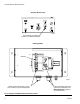
System Electrical Schematic System Electrical Schematic Non-Hazardous Area NON-HAZARDOUS AREA OPERATOR INTERFACE DC OK +24 VDC COMMON COMMON + + - 1 2 POWER SUPPLY L1 N L1 85-250 VAC N LINE FILTER L1 N GND 1 2 3 POWER HARNESS BARRIER BOARD J1 1 2 3 4 5 J5 1 2 3 J4 1 2 3 UNUSED UNUSED UNUSED UNUSED UNUSED L1 N GND GND LUG GND N L1 85-250 VAC 1 POWER 2 ROCKER 1A SWITCH 1B 2A 2B OPEN OPEN HARNESS L1 TERMINAL N BLOCK GND +12VDC I/S (RED) COM (BLACK) SHIELD CABLE +24VDC OPEN COMMON (
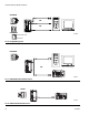
Parts Parts 15V331 Gateway Ethernet Kit (shown) 15V963 Gateway DeviceNet Kit 15V964 Gateway Profibus Kit Ref. No. 1 2 3 4 5 6 7 8▲ 9 10 10a 10b 10c Part No.
Parts 1, 2 10a, b, or c 20a or b 4 14 13 7, 9, 12 11 12 3 USB Port (ref item 23) Screw Location (item 25) 8 TI12930a 5 6 Wiring Diagrams 10 14 4 17 DRRJ45 Network Terminals 1 2 3 4 5 6 7 8 shsh 18 15 14 16 TI12929a 17 1 2 3 A B SH ProMix 2KS EasyKey RS485 Network Terminals TI12931a 312785C To 4 To 10 18 TI12932a 41
Appendix A: DeviceNet™ Slave Communication Appendix A: DeviceNet™ Slave Communication Overview This appendix describes the Gateway’s support for DeviceNet and details the configuration steps necessary to use this feature. It does not provide a detailed description of DeviceNet, but only a brief introduction, necessary to define the terms that are used throughout the remainder of this document.
V+ CAN_H DRAIN CAN_L LED V- Appendix A: DeviceNet™ Slave Communication TI13963a PLC Connection DeviceNet Option Card XCDN NET STS VCAN_L DRAIN CAN_H V+ TI13962a FIG.
Appendix A: DeviceNet™ Slave Communication About DeviceNet • I/O Poll Connection: The Poll connection is an I/O connection over which Poll command and response messages are transferred. The Poll command is transmitted by the master, and is directed to a single slave device. The slave device in turn responds with a Poll response message. Both the Poll command and Poll response messages can contain any number of bytes.
Appendix A: DeviceNet™ Slave Communication Hardware To use DeviceNet on the Gateway, an option card must first be installed. The option card provides the hardware necessary to support the CAN physical layer specification as required by the DeviceNet standard. Configuring the option card is a two-stage process; first the option card must be selected in Gateway (DeviceNet Option Card), and then the ‘DeviceNet Predefined Group 2 Server Driver’ configured to run on the newly created DeviceNet Interface port.
Appendix A: DeviceNet™ Slave Communication The DeviceNet Option card appears at the end of the tree. Select the DeviceNet Interface from under the DeviceNet Option Card item. On the right hand pane, click on the Edit button to open the driver picker dialog box. Select the DeviceNet Predefined Group 2 Server driver. FIG. 32. FIG. 32: Select DeviceNet Server Set the appropriate Station Address, Baud Rate, and I/O Poll Size. Make sure the Data Format Settings are set to Transform: Swap Bytes In Word. FIG.
Appendix A: DeviceNet™ Slave Communication IMPORTANT NOTE: The I/O Polled Size is determined by the settings in both the DeviceNet Master and the registered .EDS file for the Gateway. To change these settings, see Automatic Update of the EDS File on page 51 before setting up the PLC. FIG.
Appendix A: DeviceNet™ Slave Communication Create Gateway Blocks Select the DeviceNet device from the tree at the left, and add two Gateway Blocks; one for Read Data and one for Write Data, using the Add Gateway Block button on the right hand pane. FIG. 34: Add a Gateway Block Select the first Gateway Block and select the Edit button at the right. Set the block for I/O Polled Command Data, starting at element PollC 00000. FIG. 35.
Appendix A: DeviceNet™ Slave Communication NOTE: For 16-bit support, select Word as Word. For 32-bit support, select Word as Long. The latter is recommended as DeviceNet uses 32 bits integer addressing. Set the block size for 4, and the Direction for: Device To Gateway. This will be the Read Data block. FIG.
Appendix A: DeviceNet™ Slave Communication Select the second Gateway Block and set it up for I/O Polled Response Data 00000, with a length of 4, and the Direction Gateway To Device. This will be the Write Data Block. FIG. 36 shows both Gateway blocks once completed. FIG. 36: DeviceNet Block Mapping NOTE: Read and Write are from the Gateway point of view. This means the master can send data in Block A, so the Gateway can read data.
Appendix A: DeviceNet™ Slave Communication Automatic Update of the EDS File DeviceNet nodes use an EDS (Electronic Data Sheet) to describe the communications parameters available at each device on the DeviceNet network. Gateway provides an EDS file generator tool to create a file that matches your Gateway settings. This file can therefore be used to configure the Master. By design, each DeviceNet master can handle a maximum of 124 Input words and 123 Output words.
Appendix A: DeviceNet™ Slave Communication Configure the RSNetWorx for DeviceNet Software RSNetWorx for DeviceNet is used to set up and manage a DeviceNet network. To begin the configuration, launch RSNetWorx for DeviceNet from your development PC. Make sure that the .EDS file validation is successful. Start a new network by selecting: File>New>DeviceNet Configuration.
Appendix A: DeviceNet™ Slave Communication Review the EDS registration, and finish the process. Select the DeviceNet Master by navigating in the tree on the left hand side. Navigate to: DeviceNet>Category>Communication Adapter>1756-DNB/A. Select the appropriate Major Rev and drag it into the network workspace at the right. Select the Gateway Slave by navigating in the tree on the left. Navigate to: DeviceNet>Vendor>Graco Controls>Generic Device.
Appendix A: DeviceNet™ Slave Communication Make sure that the Strobed or Change of State boxes are not selected. In the Polled section, verify that the Input and Output sizes are 16 bytes. These must match the I/O Poll Size selections made above in the Gateway. In DeviceNet networks, 4 bytes constitute a full word. Therefore the 16 bytes selection represents 4 full words of addressable 32-bit data. Select the Input tab. Verify that the four words of Gateway-SERVER data are mapped to YourDNBSlot:I.
Appendix A: DeviceNet™ Slave Communication Configure the Allen Bradley ControlLogix PLC Allen Bradley ControlLogix PLCs are programmed with RSLogix 5000 programming software. To begin the DeviceNet configuration, launch RSLogix 5000 from your development PC. Create a ControlLogix program containing a valid DeviceNet Scanner. In this application a 1756-DNB was used. FIG.
Appendix A: DeviceNet™ Slave Communication Configure the DeviceNet Scanner to be address 0. Make sure to set up the 32-bit Input and Output memory spaces for a size of 32 (to match the configuration made above in both Gateway and RSNetWorx for DeviceNet). Select the RSNetWorx tab, and navigate to the RSNetWorx for DeviceNet configuration that you have previously created. Open the configuration from here and download it to the network. FIG.
Appendix B: Profibus™ DP Slave Communication Appendix B: Profibus™ DP Slave Communication Overview This appendix describes the Gateway’s support for Profibus DP and details the configuration steps necessary to set up a Graco Gateway with an S7300 PLC, CPU315-2DP via Profibus. It does not provide a detailed description of Profibus, but only a brief introduction, necessary to define the terms that are used throughout the remainder of this document.
Appendix B: Profibus™ DP Slave Communication About Profibus DP Profibus DP communication takes the form of block exchange. Profibus blocks are made of memory bytes where 2 bytes make a word and 4 bytes a double word, or Dword. A block is a range of consecutive byte addresses and is unidirectional. This means the PLC will exchange data read only and write only blocks with DP slave units. Addresses in each device are independent and only relevant to the device for its own program.
Appendix B: Profibus™ DP Slave Communication Setup the PLC The Siemens Simatic Manager software is used to set up the S7300 PLC. The following figures and explanations are extracted from this software. Install the GSD file The first step is to install the GSD file so Simatic is able to map data blocks to our device. Contact Graco Technical Assistance for Profibus GSD files. Start Simatic Manager and open or create a new PLC project. Select the Simatic 300 Station in the navigation pane as shown in FIG.
Appendix B: Profibus™ DP Slave Communication Click Browse to select the folder were the GSD file downloaded previously is, select the file and click Install. FIG. 51. Once the GSD file is installed successfully, the PLC hardware setup can be opened again by doing Station and selecting the latest opened file which should be number 1. If this is a new project, configure your PLC with the right modules. FIG.
Appendix B: Profibus™ DP Slave Communication Setup the Profibus Network The following steps show how to set up the Profibus DP network. Skip these steps if your PLC application already possesses a Profibus DP network. In the floating window that represents the PLC, double click the DP area to open the properties window as shown in FIG. 52. FIG.
Appendix B: Profibus™ DP Slave Communication In the General tab, click the properties button to open the Profibus properties. FIG. 53. FIG. 53: Open Profibus Properties In the properties window, go to the Parameters tab and click on the New button to create a new network. FIG. 54. FIG.
Appendix B: Profibus™ DP Slave Communication Select the Network Settings tab and choose the Transmission Rate that fits the application. In this example, it will be 12 Mbps. The profile should be DP. FIG. 55. FIG. 55: Set Transmission Rate Close the popup windows by clicking OK. HWConfig should now show the Profibus DP master system next to the PLC. FIG. 56. FIG.
Appendix B: Profibus™ DP Slave Communication Add the Graco Gateway to the Profibus Network To add the Graco Gateway to the Profibus network, drag the Gateway Profibus Card from the Catalog navigation situated on the right hand side of HWConfig to the Profibus DP Master System. The card is situated under Profibus DP>Additional Field Devices>MMI. In the properties window that popped up, select the Profibus address the Gateway will take on the network. This address should be unique.
Appendix B: Profibus™ DP Slave Communication The Gateway is now on the Profibus DP network and selected. HWConfig shows the slots available under the Gateway to configure the data blocks to exchange. Just drag and drop one of the data blocks available under the Gateway Profibus Card in the slot number 1. Simatic will automatically assign a start address (byte number) in the respective Input and output columns depending of the block type chosen. In this example, 64 words in and 64 words out.
Appendix B: Profibus™ DP Slave Communication Graco Gateway Setup Once the PLC is setup, the Gateway can be programmed to fit its configuration. NOTE: For a Gateway to communicate on Profibus DP, a Profibus Option card has to be fitted in the unit. Refer to the device manual to find the proper option card and installation procedure. Setup the Profibus Communication Enter the communication module and select the Gateway. On the right hand pane, click the Edit button to select the Option card.
Appendix B: Profibus™ DP Slave Communication The option card appeared in the communication tree. Select the Profibus Interface and click the Edit button to select a driver. Click OK to pick the Profibus DP driver. FIG. 60. FIG. 60: Select Profibus Server Graco Gateway now displays the driver settings where the Station Address can be changed. This address is the Gateway address on the Profibus network. In our example, this address is 5 as setup in the PLC earlier.
Appendix B: Profibus™ DP Slave Communication Setup Tags Once the communication is set up, tags can be created to access the PLC blocks. This is where the section Setup the Profibus Communication, page 66, is important. First, create a variable that correspond to the data type required. In this example, an integer. FIG. 62. FIG. 62: Create a Variable Select the variable and rename it eventually.
Appendix B: Profibus™ DP Slave Communication In the popup window, select the block type required. Two choices are available: • Input block: The terminology input is from the Siemens perspective. Therefore this will be a block the Gateway will write to. The tag mapped to an input block has to be set up as Write Only. • Output block: The terminology output is from the Siemens perspective. Therefore this will be a block the Gateway will read from.
Appendix B: Profibus™ DP Slave Communication How Addressing Works The Gateway addressing follows a different scheme, as shown in FIG. 67. PLC addressing is in byte and uses the scheme shown in FIG. 66. This means that the address number will be different when accessing words or Dwords in the Gateway data tags than the PLC. Table 6 shows the address relationship for integer tags mapped as word in the Gateway.
Appendix B: Profibus™ DP Slave Communication Useful Formulas The following formula can be used to find the byte number from a word address: ByteAddress = PLCOffset + (WordAddress x 2), where: • ByteAddress is the address we are looking for in the PLC • PLCOffset is the first byte number in the complete block mapping in the PLC, here 256 • WordAddress is the address mapped in the Gateway.
Appendix C: Graco Gateway to ControlLogix via Ethernet IP Appendix C: Graco Gateway to ControlLogix via Ethernet IP Overview Introduction This appendix describes the configuration steps necessary to establish a communication path between the Graco Gateway and a ControlLogix unit. You will need either a 1756-ENET/B or a 1756-ENBT/A together with a Logix5550 controller.
Appendix C: Graco Gateway to ControlLogix via Ethernet IP ControlLogix Configuration h. Select the Port Configuration Tab from the Module Properties window. See FIG. 70. 1. Run the RSLogix 5000 program and create a new configuration. i. Enter the IP Address and Subnet Mask. The IP Address must match the IP Address entered in the Properties window (FIG. 69). j. Apply the settings using the Set button. k.
Appendix C: Graco Gateway to ControlLogix via Ethernet IP IP Address Subnet Mask Set Button FIG. 70. Port Configuration Window FIG. 71.
Appendix C: Graco Gateway to ControlLogix via Ethernet IP e. In the Name field, enter a descriptive name to identify the module. See FIG. 72. f. In the Address/Host Name field, enter the IP Address of the Graco Gateway. i. Enter 1 in the Configuration Connection Point and a size of 0. Configuration data is not supported by the Gateway. j. Press Finish to add the Gateway to the I/O configuration. g. Enter 2 in the Input Assembly Connection Point and a size of 2.
Appendix C: Graco Gateway to ControlLogix via Ethernet IP See FIG. 73. You should now see a new ETHERNET-MODULE Gateway_HMI branch of the 1756-ENET/B node in the I/O Configuration view. You should also see three new entries in the Controller Tags view: • • • 4. Download the new I/O configuration to the controller. Once the download is complete, the controller will automatically establish a new Class1 connection with the Gateway.
Appendix C: Graco Gateway to ControlLogix via Ethernet IP Graco Gateway Configuration 1. Ethernet Settings. Set the IP Address to 192.168.2.101. This should match the Address/Host Name entered in FIG. 72. 2. Protocol Settings. Select the Ethernet/IP Slave Adapter communications driver. The ENET/B module prefixes all output data with a header containing status information about the originator’s run/idle state.
Appendix C: Graco Gateway to ControlLogix via Ethernet IP The following settings mirror the I/O settings of the ControlLogix configuration detailed earlier. a. Input Connection Point. Create a Gateway block configuration (see Table 7). Table 7: Input Connection Points Connection Point 2 Data Offset 0000 Data Type Long as Long Block Size 2 Direction Graco Gateway to Device b. 4. Data Mapping.
Dimensions Dimensions 16.57 in. (420.9 mm) 4.52 in. (114.8 mm) 15.07 in. (382.8 mm) 8.71in. (221.2 mm) 5.31in. (134.
Dimensions 80 312785C
Technical Data Technical Data Electrical power . . . . . . . . . . . . . . . . . . . . . . . . . . . . 24 Vdc, +/- 10%. 200 mA minimum without expansion card; 1 Amp maximum with expansion card fitted. Requires Class 2 or SELV rated power supply. Communication ports USB/PG Ports . . . . . . . . . . . . . . . . . . . . . . . . . . Adheres to USB specification 1.1. Device only using Type B connection. Serial Ports . . . . . . . . . . . . . . . . . . . . . . . . . . . .
Graco Standard Warranty Graco warrants all equipment referenced in this document which is manufactured by Graco and bearing its name to be free from defects in material and workmanship on the date of sale to the original purchaser for use. With the exception of any special, extended, or limited warranty published by Graco, Graco will, for a period of twelve months from the date of sale, repair or replace any part of the equipment determined by Graco to be defective.