Instructions-Parts Dump Valve and Third Purge Valve Kits 312786G EN For use with ProMix® 2KS Electronic Proportioners. For professional use only. See page 2 for kit part numbers and maximum working pressure. Important Safety Instructions Read all warnings and instructions in this manual. For complete warnings and instructions see your proportioning system manual. Hazard symbols refer to specific procedure risks. Save all instructions.
Kits Kits 15V821 Dump Valve Kit For wall mount ProMix 2KS Electronic Proportioners 3000 psi (21 MPa, 210 bar) Maximum Fluid Working Pressure 100 psi (0.7 MPa, 7 bar) Maximum Air Working Pressure See pages 3 and 14 15V822 Robo Dump Valve Kit For robo mount ProMix 2KS Electronic Proportioners 300 psi (2.1 MPa, 21 bar) Maximum Fluid Working Pressure 100 psi (0.
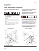
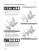
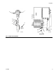
Installation Installation 15V821 Dump Valve Kit for Wall Panel NOTE: These instructions show this kit being installed on the A side. It may also be installed on the B side. 5. Install the dump valve assembly (includes 1, 2, 4, and 11) in a slot of the flange (F) at the back of the wall panel. Secure with the nut (8). 6. Install the elbow (6) in the open port of the dump valve adapter (2). Connect a 1/4 npsm(f) hose (12) between the elbow (6) and nipple (19). 1.
Installation Wall Panel RoboMix Panel Dump Valve B Dump Valve A 3rd Flush Valve TI12655a Dump Valve B Dump Valve A GFB2 3rd Flush Valve GFB1 TI13116a FIG. 2: Solenoid Manifolds J15-1 J15-2 J15-5 J15-6 J8-1 J8-2 J8-3 J8-4 J8-5 J8-6 3rd Purge Valve Dump Valve A Dump Valve B Auto Dump Valve A (GFB1) Auto Dump Valve B (GFB2) Wire Color J15-1 J15-5 J8-5 J8-3 J8-1 Red J15-2 J15-6 J8-6 J8-4 J8-2 Black FIG.
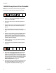
Installation 15V354 Third Flush Valve Kit for Wall Panel 7. Connect the tubing (13, 14) between the solenoid manifold and the tube fittings (T) on the flush valve (2). See System Pneumatic Schematic, page 10. 1. Shut off the air and fluid supply to the ProMix 2KS. 2. Relieve pressure. See your ProMix 2KS Operation Manual. 3. See FIG. 4. Remove the air flush valve (AFV) from the fluid mix manifold (FM) and set it aside. 6 1 8 FM TI12956a FIG.
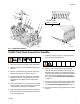
Installation 15V822 Dump Valve Kit for RoboMix NOTE: These instructions show this kit being installed on the B side. It may also be installed on the A side. 1. See FIG. 7. Shut off the fluid supply to the dose valve (V) in the RoboMix. 2. Actuate the dose valve to relieve fluid pressure in the valve. 3. Relieve fluid pressure upstream and downstream of the dose valve. See your ProMix 2KS Operation Manual. 4. Remove the plug from the dose valve adapter.
Installation 1 T 10 2 3 6 TI12655a Dump Valve B 5 V Dump Valve A 8 4 11 9 TI13047a TI13045a FIG. 7: 15V822 Kit Installation 15V202 Third Flush Valve Kit for RoboMix 7. Install the o-ring (2), seat (1), o-ring (6), and third flush valve (5) in the adapter (3). 1. Shut off the air and fluid supply to the ProMix 2KS. 2. Relieve pressure. See your ProMix 2KS Operation Manual. 3. See FIG. 8. Remove the plug (A) from the air flush valve (AFV). Install an o-ring (6) in this port. 4.
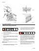
Installation 9 5 T 6 1 3 6 TI12655a 2 8 4 10 TI13046a TI13047a FIG. 8: 15V202 Kit Installation 15X247 Auto Dump Valve Kit 6. Connect a 1/4 npsm(f) dump hose (not supplied) to the 1/4 npsm(m) threaded stud at the bottom of the adapter (2). When the gun closes, the dump valve opens and fluid is dumped through the stud. 1. Close the component A and component B shutoff valves on the fluid manifold. 2. Trigger the gun to relieve fluid pressure downstream of the fluid manifold. 3. See FIG. 9.
Installation 1 T 7 6 3 8 GFB1 GFB2 2 J8 (see FIG. 3 for details) 9 5 TI14283b 4 TI13116a Wall Panel FIG.
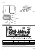
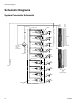
Schematic Diagrams Schematic Diagrams System Pneumatic Schematic COLOR CHANGE CONTROL A B E BE OS CL 2 TU / 53 N E OP DOSE A VALVE 12 VDC 4-WAY SOLENOID A B E BE OS CL 2 TU 5/3 N E OP A B E BE OS CL 2 TU 5/3 N E OP DOSE B VALVE 12 VDC 05 AIR INPUT 4-WAY SOLENOID CONTROL AIR 3/8 AIR FILTER MANUAL DRAIN 5 MICRON WALL MOUNT ONLY 4-WAY SOLENOID A B 12 VDC A B AIR EXHAUST MUFFLER PURGE AIR PURGE A VALVE E BE OS CL 2 TU 5/3 N E OP PURGE B VALVE E BE OS CL 2 TU / 53 N E OP PURGE C VALVE (
Schematic Diagrams Tubing Schematic B3 13 B1 13 GFB1-P A2 GFB2-P A6 B7 B5 DB AT A4 DA A8 TI13857a B1 B3 B5 B7 GFB1-C TI13858a GFB2-C GFB1-A GFB2-A TI13862a A2 A4 A6 A8 DA DB GFB1-P GFB1-A ATOM-1 GFB1 GFB2 GFB1-C GFB1-S GFB2-P GFB2-A GFB2-C GFB2-S TI13863a 312786G GFB1-S GFB2-S ATOM-1 TI13861a ATOM-2 ATOM-2 TI13860a 11
Schematic Diagrams Table 1: Tubing Chart Color Description Starting Point Ending Point Tube OD in. (mm) Tube Ref. No.
Schematic Diagrams System Electrical Schematic Hazardous Area HAZARDOUS AREA FLUID PANEL CONTROL BOX FLUID PANEL CONTROL BOARD J3 J12 J10 1 +12VDC I/S 2 COM 3 SHIELD J13 J5 MH2 J11 3X CABLE 1 2 3 4 5 6 PWR (RED) COM (BLACK) SIG (WHITE) SHIELD/GRN PWR (RED) COM (BLACK) SIG (WHITE) SHIELD/GRN PWR (RED) COM (BLACK) SIG (WHITE) SHIELD/GRN 1 2 3 4 5 6 UNUSED UNUSED UNUSED UNUSED UNUSED UNUSED 1 2 3 4 5 6 FLOW METER A FLOW METER SOLVENT V/P ANALOG OUT (WHT) PRESS.
Parts Parts 15V821 Dump Valve Kit for Wall Panel 18 1* 19 *14 *11 *4 *2 15 A B 12 6 13 8 7 TI12742b Ref. No. 1* Part No. Description Qty 24W310 VALVE, dispense; includes 14; see 1 manual 312782 2* 15T717 ADAPTER, dump valve 1 4*† 111457 O-RING; ptfe 1 6 114342 ELBOW; 1/4 npt (mbe) 1 7 n/a TUBE; nylon; 5/32 in. (4 mm) OD; 1 2 ft (0.61 m) 8* n/a NUT, hex; 9/16-18 1 9 121324 VALVE, solenoid, dump valve 1 11*† n/a SEAT, dump valve; sst 1 9 TI13116a Ref. No. 12 13 Part No.
Parts 15V354 Third Flush Valve Kit for Wall Panel 6 8 ‡11 3 7 5 1 2 ‡4 TI12953a ‡6 10 9 12 Ref. No. 1 2 3 4‡ 5 6‡ 7 8 9 10 Part No. Description Qty 15U673 BLOCK, double valve mount 1 15X303 VALVE, dispense; includes item 4; 1 see manual 312782 15T600 ADAPTER, valve 1 n/a O-RING; ptfe 2 101970 PLUG, pipe; 1/4 npt 3 109450 O-RING; ptfe 5 n/a SCREW, cap, socket-hd; 5/16-24 x 2 3/4 in. (19 mm) 109031 SCREW, cap, socket-hd; 5/16-24 x 2 1 in.
Parts 15V822 Dump Valve Kit for RoboMix 1 TI12655a 10 2 Dump Valve B 3 Dump Valve A 6 5 4 8 11 TI13047a 9 TI13045a Ref. No. 1 2 3 4 5 6 8 9 10 16 Part No. Description Qty 15X304 VALVE, dispense; includes item 10; 1 see manual 312782 15V888 RETAINER, seat, RoboMix 1 15U713 VALVE, adapter; RoboMix 1 121795 VALVE, solenoid, 4-way 1 15U720 HOSE; 1/4 npt (mbe); 15-1/2 in.
Parts 15V202 Third Flush Valve Kit for RoboMix 9 5 6 1 3 2 TI12655a 8 4 10 TI13046a Ref. No. 1 2 3 4 5 6 8 9 10 13 TI13047a Part No. 15V888 109450 15U715 501867 15X304 Description Qty RETAINER, seat, RoboMix 1 O-RING; ptfe 1 VALVE, adapter; RoboMix 1 VALVE, check 1 VALVE, dispense; includes item 6; 1 see manual 312782 n/a O-RING; ptfe 2 121795 VALVE, solenoid, 4-way 1 111328 CONNECTOR; 10-32 x 5/32 in. (4 1 mm) OD tube 110420 SCREW, cap, socket-hd; 10-24 x 4 1-1/2 in.
Parts 15X247 Auto Dump Valve Kit 1 7 6 3 8 GFB1 GFB2 2 9 5 4 TI14283a Ref. No. 1 2 3† 4 5 6† 7† 8 9 Part No. 24W310 15T717 111457 n/a 121324 n/a n/a C20482 111328 Description VALVE, dispense; includes 7 ; see manual 312782 ADAPTER, dump valve O-RING; ptfe TUBE; nylon; 5/32 in. (4 mm) OD; 5 ft (1.52 m) VALVE, solenoid, dump valve SEAT, dump valve; sst O-RING; ptfe NIPPLE; 1/4 npt CONNECTOR; 10-32 x 5/32 in. (4 mm) OD tube TI13116a Qty 1 1 1 1 1 1 1 1 1 † Order Kit 16A560 to replace a single seat.
Notes Notes 312786G 19
Graco Standard Warranty Graco warrants all equipment referenced in this document which is manufactured by Graco and bearing its name to be free from defects in material and workmanship on the date of sale to the original purchaser for use. With the exception of any special, extended, or limited warranty published by Graco, Graco will, for a period of twelve months from the date of sale, repair or replace any part of the equipment determined by Graco to be defective.