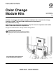
Instructions-Parts Color Change Module Kits 312787G EN Includes color change valve stack and control module to add or expand color change function on ProMix® 2KS and ProMix 3KS Electronic Proportioners. For professional use only. Approved for use in explosive atmospheres only when used in conjunction with ProMix 2KS or ProMix 3KS Electronic Proportioners. See page 3 for model information, including maximum working pressure. Important Safety Instructions Read all warnings and instructions in this manual.
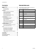
Related Manuals Contents Related Manuals . . . . . . . . . . . . . . . . . . . . . . . . . . . 2 Models . . . . . . . . . . . . . . . . . . . . . . . . . . . . . . . . . . . 3 Low Pressure Kits . . . . . . . . . . . . . . . . . . . . . . . . 3 High Pressure Kits . . . . . . . . . . . . . . . . . . . . . . . 3 Installation . . . . . . . . . . . . . . . . . . . . . . . . . . . . . . . . 4 Install Color Change Control Module . . . . . . . . . 4 Install Color Valve Stacks . . . . . . . . . . . . . . . . . .
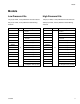
Models Models Low Pressure Kits High Pressure Kits 100 psi (0.7 MPa, 7.0 bar) Maximum Air Inlet Pressure 100 psi (0.7 MPa, 7.0 bar) Maximum Air Inlet Pressure 300 psi (2.1 MPa, 21 bar) Maximum Fluid Working Pressure 3000 psi (21 MPa, 210 bar) Maximum Fluid Working Pressure Kit Part No. Series Description Kit Part No.
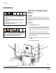
Installation Installation Install Color Change Control Module • To avoid electric shock, turn off equipment power and shut off power at main circuit breaker before installing. • All electrical wiring must be done by a qualified electrician and comply with all local codes and regulations. • Do not substitute system components as this may impair intrinsic safety. Location Install the color change control module (101) near the fluid station. The module is approved for use in a hazardous location.
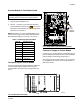
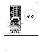
Installation Connect Module to Fluid Station Board NOTICE To avoid damaging circuit board when servicing, wear grounding strap on wrist and ground appropriately. 1. Remove the Fluid Station cover. 2. See FIG. 1. Connect a 5-pin electrical cable (EC) from the labeled connection port (J11) on the J11 (Color Change Module) fluid station control board to the color change board. Also see FIG. 2 and FIG. 5.
Installation 6 312787G
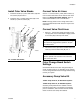
Installation Install Color Valve Stacks Connect Valve Air Lines 1. Install the bracket (17) on the fluid station (FS) with two screws (20). See FIG. 4. See FIG. 1. Connect 5/32 in. (4 mm) OD air tubes (11) from the valve solenoids to the air inlets of each valve. Refer to the System Pneumatic Diagram, page 14, and the label inside the color control module. 2. Install the color or catalyst valve stack (VS) to the bracket (17) with two screws (20).
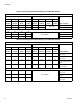
Installation Table 2: Color Change Board Switch Settings for ProMix 2KS Systems Two Color Change Boards Color Change Board 1 Color Change Board 2 S3 S6 S5 S4 S3 S6 S5 S4 Termination Resistor Board ID Catalyst On/Off Color On/Off Termination Resistor Board ID Catalyst On/Off Color On/Off OFF ON ON ON ON OFF OFF ON OFF ON ON NOT USED OFF Effect on System 4 catalyst/30 color valves 0 catalyst/30 color valves One Color Change Board ON ON ON ON ON ON ON OFF ON ON OFF O
Installation Switch S3-S6 Positions ON ON OFF OFF TI13661a S6 S4 S5 J7 S3 FIG. 5.
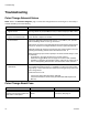
Troubleshooting Troubleshooting Color Change Solenoid Valves NOTE: Refer to the Schematic Diagrams, page 14. If the color change valves are not turning on or off correctly, it could be caused by one of the following. Cause Solution 1. Air regulator pressure set too high or too low. Check air pressure. 80-90 psi (550-630 kPa, 5.5-6.3 bar) is commonly used. Do not go below 75 psi (0.52 MPa, 5.2 bar) or above 100 psi (0.7 MPa, 7 bar). 2. Air or electrical lines damaged or connections loose.
Troubleshooting Replace a Solenoid 1. Remove air supply pressure from the system. Remove the color change module cover (30). 2. Disconnect the 2 solenoid wires from the color change board (15). See FIG. 7, the Color Change Module Electrical Schematic on page 15, and the System Electrical Schematic on page 17. 3. Unscrew 2 screws (P) and remove the solenoid (4). See FIG. 6. Replace the Color Change Board Fuse NOTE: Replacing the fuse with a non-Graco fuse voids the IS system safety approval. Fuse 4.
Troubleshooting Color Change Board Diagnostics See FIG. 7 and Table 4 to troubleshoot the color change board. Also see the System Electrical Schematic on pages 16 and 17. 16 J8, Pin 1 D33 16 D34 D43 D31 D44 D29 J9, Pin 1 J15, Pin 1 D39 D41 D32 D35 D38 J16, Pin 1 D27 D37 J14, Pin 1 D45 D30 D46 D28 J10, Pin 1 D36 16 16 D9 16 D10 D8 F1 16 J7 J11 FIG.
Troubleshooting Table 4: Color Change Board Diagnostics LED Connector and Pin Nos. Board 1 Signal Description Board 2 Signal Description Diagnosis D8 n/a Board OK Board OK Blinks (heartbeat) during normal operation. D9 n/a Communication (yellow) Communication (yellow) Turns on when board is communicating with ProMix 2KS. D10 J7 Power Power Turns on when power is supplied to the board.
Schematic Diagrams Schematic Diagrams System Pneumatic Diagram COLOR CHANGE CONTROL A B SE BE CLO 2 TU 5/3 N E OP DOSE A VALVE 12 VDC 4-WAY SOLENOID A B SE BE CLO 2 TU 5/3 N E OP DOSE B VALVE 12 VDC 05 AIR INPUT 4-WAY SOLENOID CONTROL AIR 3/8 AIR FILTER MANUAL DRAIN 5 MICRON WALL MOUNT ONLY PURGE AIR A B SE BE CLO 2 TU 5/3 N E OP PURGE A VALVE 4-WAY SOLENOID A B 12 VDC A B AIR EXHAUST MUFFLER SE BE CLO 2 TU 5/3 EN OP PURGE B VALVE SE BE CLO 2 TU 5/3 N E OP PURGE C VALVE (OPTIONAL)
Schematic Diagrams Color Change Module Electrical Schematic WIRING DIAGRAM COLOR 8 (21) COLOR 7 (20) COLOR 6 (19) COLOR 5 (18) COLOR 4 (17) COLOR 3 (16) COLOR 2 (15) COLOR 1 (14) COLOR FLUSH (13) 312787G +12VDC COM +12VDC COM +12VDC COM +12VDC COM +12VDC COM +12VDC COM +12VDC COM +12VDC COM +12VDC COM J8 J15 J14 J9 J16 J10 COM +12VDC COM +12VDC COM +12VDC COM +12VDC COM +12VDC COM +12VDC COM +12VDC COM +12VDC COM +12VDC COLOR 9 (22) COLOR 10 (23) COLOR 11 (24) COLOR 12 (25) CATALYST 4 (26) CATAL
Schematic Diagrams System Electrical Schematic Non-Hazardous Area NON-HAZARDOUS AREA OPERATOR INTERFACE DC OK +24 VDC COMMON COMMON + + - 1 2 POWER SUPPLY L1 N L1 85-250 VAC N LINE FILTER L1 N GND 1 2 3 POWER HARNESS BARRIER BOARD J1 1 2 3 4 5 J5 1 2 3 J4 1 2 3 UNUSED UNUSED UNUSED UNUSED UNUSED L1 N GND GND LUG GND N L1 85-250 VAC 1 POWER 2 ROCKER 1A SWITCH 1B 2A 2B OPEN OPEN HARNESS L1 TERMINAL N BLOCK GND +12VDC I/S (RED) COM (BLACK) SHIELD CABLE +24VDC OPEN COMMON (50' STD.
Schematic Diagrams System Electrical Schematic Hazardous Area HAZARDOUS AREA FLUID PANEL CONTROL BOX FLUID PANEL CONTROL BOARD J3 J12 J10 1 +12VDC I/S 2 COM 3 SHIELD J13 J5 MH2 J11 3X CABLE 1 2 3 4 5 6 PWR (RED) COM (BLACK) SIG (WHITE) SHIELD/GRN PWR (RED) COM (BLACK) SIG (WHITE) SHIELD/GRN PWR (RED) COM (BLACK) SIG (WHITE) SHIELD/GRN 1 2 3 4 5 6 UNUSED UNUSED UNUSED UNUSED UNUSED UNUSED 1 2 3 4 5 6 FLOW METER A FLOW METER SOLVENT V/P ANALOG OUT (WHT) PRESS.
Parts Parts Low Pressure Color Change Kits Kit Part No.
Parts Color Change Kits Parts 101 Screw Location (item 32) 30 11 11 103 13 102 19 TI12828b 17 20 20 TI12829a 312787G 19
Parts Color Change Control Modules (Ref. No. 101; see page 18) Ref. No. Part No.
Parts 13 6 9 2 5 14 4 9 18 7 8 TI12826a 312787G 21
Parts 277752 2-Color Control Module Ref. No. 2 3 4 5 7 8 9 11 12 13 14 15 16 17 18 19 20 26 29 30 31 32 Part No. Description 15T636 103833 121324 121628 121487 109193 100139 598095 15T635 590332 119162 256172 112324 15U927 C06061 24N345 C19798 116343 115671 15T752 123690 n/a Qty 1 2 3 12 1 3 2 1 1 1 1 1 6 1 1 1 4 1 1 1 1 4 MANIFOLD, color change control SCREW, machine, pan hd; 10-32 x 3/8 in. (10 mm) (behind panel 12 and manifold 2) VALVE, solenoid SCREW, self-sealing; 4-40 x 1/4 in.
Parts 278095 1 Catalyst/1 Flush Control Module (0 Color) Ref. No. Part No. 2 3 4 5 7 8 9 11 12 13 14 15 16 17 18 19 20 26 29 30 31 32 15T636 103833 121324 121628 121487 109193 100139 598095 15T635 590332 119162 256172 112324 15U927 C06061 24N345 C19798 116343 115671 15T752 123690 n/a Description Qty 1 2 2 14 1 2 2 1 1 1 1 1 6 1 1 1 4 1 1 1 1 4 MANIFOLD, color change control SCREW, machine, pan hd; 10-32 x 3/8 in.
Dimensions Dimensions 16.57 in. (420.9 mm) 4.52 in. (114.8 mm) 15.07 in. (382.8 mm) 8.71 in. (221.2 mm) 5.31 in. (134.
Technical Data Technical Data Air Specifications Maximum Air Input Pressure . . . . . . . . . . . . . . . . . . . 100 psi (0.7 MPa, 7.0 bar) Minimum Air Input Pressure. . . . . . . . . . . . . . . . . . . . 75 psi (0.52 MPa, 5.2 bar) Fluid Specifications Maximum Fluid Working Pressure . . . . . . . . . . . . . . . Low Pressure Valve Stacks: 300 psi (2.1 MPa, 21 bar) High Pressure Valve Stacks: 3000 psi (21 MPa, 210 bar) Fluid Wetted Parts . . . . . . . . . . . . . . . . . . . . . . . . . . .
Graco Standard Warranty Graco warrants all equipment referenced in this document which is manufactured by Graco and bearing its name to be free from defects in material and workmanship on the date of sale to the original purchaser for use. With the exception of any special, extended, or limited warranty published by Graco, Graco will, for a period of twelve months from the date of sale, repair or replace any part of the equipment determined by Graco to be defective.