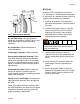
Operation Husky® 1050A UL-Listed Diaphragm Pumps 313597E EN Model 647016, Evacuation and Transfer Pump For use in general fuel transfer applications. 100 psi (0.7 MPa, 7.0 bar) Maximum Fluid Working Pressure 100 psi (0.7 MPa, 7.0 bar) Maximum Air Input Pressure Model 647648, Fuel Dispense Pump For use in petroleum product dispense systems in accordance with the United States Flammable and Combustible Liquids Code (NFPA 30) and the Automotive and Marine Service Station Code (NFPA 30a).
Related Manual Contents Related Manual . . . . . . . . . . . . . . . . . . . . . . . . . . . . 2 To Order a New Pump: . . . . . . . . . . . . . . . . . . . . . . 3 To Order Parts for Your Existing Pump . . . . . . . . . 3 Models . . . . . . . . . . . . . . . . . . . . . . . . . . . . . . . . . . . 4 UL Listing Details . . . . . . . . . . . . . . . . . . . . . . . . . . 4 Warnings . . . . . . . . . . . . . . . . . . . . . . . . . . . . . . . . . 5 Installation . . . . . . . . . . . . . . . . . . . . . . . .
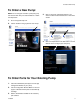
To Order a New Pump: To Order a New Pump: NOTE: Do not configure and order a pump using only this manual. Work with your Graco distributor or follow the steps below. 3. Click on the Husky 1050 Pump Selector, your choice of either the download version or the online version. 1. Go to www.gracohusky.com. 2. Click on Toolbox in the gray banner near the top. 4. Click on Pump Selector in the blue banner. Use the Selector Tool to configure your new pump. To Order Parts for Your Existing Pump 1.
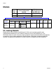
Models Models Pump size and material 1050A Graco Part Graco Configuration Number Maximum Working Pressure psi (MPa, bar) 647016 647648 1050A-AU1AA1TPACTP-1050A-AU3AA1TPACTP-- 100 (0.7, 7.0) 50 (0.35, 3.
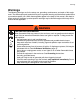
Warnings Warnings The following warnings are for the setup, use, grounding, maintenance, and repair of this equipment. The exclamation point symbol alerts you to a general warning and the hazard symbol refers to procedure-specific risk. When these symbols appear in the body of this manual, refer back to these warnings. Additional, product-specific warnings may be found throughout the body of this manual where applicable.
Warnings WARNING EQUIPMENT MISUSE HAZARD Misuse can cause death or serious injury. • Do not operate the unit when fatigued or under the influence of drugs or alcohol. • Do not exceed the maximum working pressure or temperature rating of the lowest rated system component. See Technical Data in all equipment manuals. • Use fluids and solvents that are compatible with equipment wetted parts. See Technical Data in all equipment manuals. Read fluid and solvent manufacturer’s warnings.
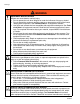
Warnings WARNING TOXIC FLUID OR FUMES HAZARD Toxic fluids or fumes can cause serious injury or death if splashed in the eyes or on skin, inhaled, or swallowed. • Read MSDS’s to know the specific hazards of the fluids you are using. • Route exhaust away from work area. If diaphragm ruptures, fluid may be exhausted with air. • Store hazardous fluid in approved containers, and dispose of it according to applicable guidelines.
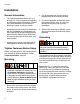
Installation Installation General Information • The Typical Installations shown in FIG. 3 through FIG. 5 are only guides for selecting and installing system components. Contact your Graco distributor for assistance in planning a system to suit your needs. • Installation and use must be in accordance with the Flammable and Combustible Liquids Code (NFPA 30) and Automotive and Marine Service Station Code (NFPA 30a) and must comply with all local, state, and federal codes. • 2.
Installation Air Line Install the air line accessories as shown in FIG. 3 through FIG. 5. Mount these accessories on the wall or on a bracket. Be sure the air line supplying the accessories is grounded. GS R ti12214a FIG. 1. Ground screw and wire Air and fluid hoses: Use only grounded hoses with a maximum of 500 ft (150 m) combined hose length to ensure grounding continuity. Air compressor: Follow manufacturer’s recommendations. Fluid supply container: Follow local code.
Installation Air Exhaust Ventilation Be sure to read and follow the TOXIC FLUID OR FUMES HAZARD warnings, page 7, and FIRE AND EXPLOSION HAZARD warnings, page 5, before operating this pump. You must vent the exhaust away from people, animals, food handling areas, and all sources of ignition when pumping flammable or hazardous fluids. Vent in accordance with local codes, or in the absence of local codes, an industry or nationally recognized code having jurisdiction over the specific installation.
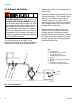
Installation C E B A D J K H Key: A Air supply line B Bleed-type master air valve (required for pump) C Air filter/regulator assembly D Air inlet E Master air valve (for accessories) G Grounded, flexible fluid supply line H Fluid drain valve (required) J Fluid shutoff valve K Grounded, flexible fluid outlet line R Ground wire (required, see page 8 for installation instructions) W Waste oil receiver R G W ti14221b FIG. 3.
Installation Key: A Air supply line B Bleed-type master air valve (required for pump) C Air filter/regulator assembly D Air inlet E Master air valve (for accessories) G Fluid suction line, flexible hose H Fluid drain valve (required) J Fluid shutoff valve K Waste oil line (to storage tank) L Fluid line, flexible hose M Control valve N Suction wand R Ground wire (required, see page 8 for installation instructions) M L N B E A C D G R K J H ti14222b FIG. 4.
Installation P X Key: A B E C B A K J C D E G H J K P R S D S H X Air supply line Bleed-type master air valve (required for pump) Air filter/regulator assembly Air inlet Master air valve (for accessories) Grounded, flexible fluid supply line Fluid drain valve (required) Fluid shutoff valve Grounded, flexible fluid outlet line Hose reel Ground wire (required, see page 8 for installation instructions) Pressure relief valve (required to limit fluid outlet pressure to 50 psi [350 kPa, 3.
Installation Fluid Pressure Relief Valve Fuel Dispense Systems (Model 647648) Fuel dispense model 647648 requires a pressure relief valve (S), Graco part 24B910, which is supplied with the pump, to prevent fluid pressure from exceeding 50 psi (350 kPa, 3.5 bar). See FIG. 5, page 13. Recommended air operating pressure is 40 psi (280 kPa, 2.8 bar) or less. As the air inlet pressure approaches 50 psi (350 kPa, 3.5 bar), the relief valve will open and vent fluid.
Operation Operation Pressure Relief Procedure Waste Oil Receiver Evacuation Systems or General Fluid Transfer Applications See FIG. 3. Trapped air can cause the pump to cycle unexpectedly, which could result in serious injury from splashing. 1. Shut off the air supply to the pump. 2. Open the dispensing valve (if used). 1. Close the pump air regulator (C) and the bleed-type master air valves (B, E). 2. Connect the pump suction hose (G) to the pump fluid inlet.
Operation Gear Oil Evacuation Systems See FIG. 4. 1. Close the pump air regulator (C) and the bleed-type master air valves (B, E). 2. Attach an appropriate wand to the suction hose. Place the wand in the differential or fluid to be pumped. 3. Place the end of the fluid hose into an appropriate container. 4. Close the fluid drain valve (H). Open the fluid shutoff valve (J). 5. Connect the air supply line to the pump air inlet (D). 6. Open the bleed-type master air valves (B, E). 7.
Maintenance Maintenance Flushing and Storage Maintenance Schedule Establish a preventive maintenance schedule, based on the pump’s service history. Scheduled maintenance is especially important to prevent spills or leakage due to diaphragm failure. Lubrication The pump is lubricated at the factory. It is designed to require no further lubrication for the life of the pump. There is no need to add an in-line lubricator under normal operating conditions.
Maintenance Torque Instructions NOTE: Fluid cover and manifold fasteners have a thread-locking adhesive patch applied to the threads. If this patch is excessively worn, the fasteners may loosen during operation. Replace screws with new ones or apply medium-strength (blue) Loctite or equivalent to the threads. If fluid cover or manifold fasteners have been loosened, it is important to torque them using the following procedure to improve sealing.
Dimensions Dimensions G F 1 3 % A & / D E 0 ti12212b ti12211b H K 5.0 in. (127 mm) J ti12213b A ..... 12.7 in. (323 mm) B ..... 14.4 in. (366 mm) C ..... 15.9 in. (404 mm) D ..... 10.9 in. (277 mm) E ..... 1.8 in. (46 mm) F...... 7.3 in. (185 mm) G ..... 14.7 in. (373 mm) H ..... 6.2 in. (158 mm) J...... 3.9 in. (99 mm) 313597E 5.5 in. (140 mm) ti14540a K .....10.2 in. (258 mm) L ......1/2 npt(f) air inlet M .....1 in. npt(f) fluid inlet ports (4) N .....1 in.
Performance Chart Performance Chart Test Conditions: Pump tested in water with inlet submerged. Cycle Rate Operating Air Pressure A 100 psi (0.7 MPa, 7.0 bar) B 70 psi (0.48 MPa, 4.8 bar) C 40 psi (0.28 MPa, 2.8 bar) Fluid Outlet Pressure — psi (MPa, bar) 28 56 84 112 140 168 196 224 252 280 120 (0.83. 8.3) 100 (0.7, 7.0) A Fluid Pressure 80 (0.55, 5.5) B 60 (0.41, 4.1) 40 (0.28, 2.8) C 20 (0.14, 1.
Technical Data Technical Data Maximum fluid working pressure Transfer Pump . . . . . . . . . . . . . . . . . . . . . . . . . . . . . . . . . . . . . . . . . . . Fuel Dispense Pump . . . . . . . . . . . . . . . . . . . . . . . . . . . . . . . . . . . . . . Air pressure operating range Transfer Pump . . . . . . . . . . . . . . . . . . . . . . . . . . . . . . . . . . . . . . . . . . . . Fuel Dispense Pump . . . . . . . . . . . . . . . . . . . . . . . . . . . . . . . . . . . . . . .
Graco Standard Husky Pump Warranty Graco warrants all equipment referenced in this document which is manufactured by Graco and bearing its name to be free from defects in material and workmanship on the date of sale to the original purchaser for use. With the exception of any special, extended, or limited warranty published by Graco, Graco will, for a period of five years from the date of sale, repair or replace any part of the equipment determined by Graco to be defective.