Instructions Oil and Grease Piston Distributors 313759A - For injecting lubricant from an intermittent pump system. Suitable for use in centralized, single-line, lubrication systems. - Models: Page 2 (includes working pressure) Important Safety Instructions Read all warnings and instructions in this manual. Save these instructions. WARNING PRESSURIZED EQUIPMENT HAZARD Fluid from the gun/dispense valve, leaks, or ruptured components can splash in the eyes or on skin and cause serious injury.
Models 3400 (Oil) / 3410 (Grease) Single Point Series Fluid 2 Part No.
500 (Oil) / 3510 (Grease) Single Point Series Fluid Part No. Fitting & Sleeve 112817 M12 x 1 121658 M10 x 1 ✔ 121659 M10 x 1 ✔ 121660 M10 x 1 ✔ 121661 M10 x 1 ✔ 121662 M10 x 1 ✔ 121663 M10 x 1 ✔ 121664 M10 x 1 ✔ 122813 M12 x 1 ✔ 122814 M12 x 1 ✔ 122815 M12 x 1 ✔ 122816 M12 x 1 ✔ 122818 M12 x 1 ✔ 122819 M12 x 1 ✔ 313759A Oil Grease ✔ Dispense Volume (cm3) Operating Pressure Range psi (bar) Viscosity .1 188 - 653 (13 - 45) NLGI 000-00 .
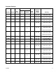
3900 (Oil) / 3910 (Grease) Single Point Series Fluid 4 Part No. Fitting & Sleeve Oil 121665 M14 x 1’5 ✔ 121666 M14 x 1’5 ✔ 121667 M14 x 1’5 ✔ 121668 M14 x 1’5 ✔ 121669 M14 x 1’5 ✔ 121670 M14 x 1,5 ✔ 121671 M14 x 1’5 ✔ 121672 M14 x 1’5 ✔ Grease 122820 M12 x 1 ✔ 122821 M12 x 1 ✔ 122822 M12 x 1 ✔ 122823 M12 x 1 ✔ 122824 M12 x 1 ✔ 122825 M12 x 1 ✔ 122826 M12 x 1 ✔ 122827 M12 x 1 ✔ Operating Pressure Range psi (bar) Viscosity .
Complete Castings Fluid Plug Color Operating Pressure Range psi (bar) Viscosity Part No. Series No. Outlets 122841 3400 2 ✔ Red 145 - 653 (10 - 45) 32 to 2000 MM^2/S .047 to 3.1 in. 2/S 122861 3400 3 ✔ Red 145 - 653 (10 - 45) 32 to 2000 MM^2/S .047 to 3.1 in. 2/S 122862 3400 5 ✔ Red 145 - 653 (10 - 45) 32 to 2000 MM^2/S .047 to 3.1 in. 2/S 122863 3410 2 White 145 - 653 (10 - 45) (Oil) 32 to 2000 MM^2/S .047 to 3.1 in.
Fluid Part No. Series No. Outlets 122890 3910 2 Oil Grease Plug Color White ✔ Operating Pressure Range psi (bar) Viscosity 145 - 653 (10 - 45) (Oil) 32 to 2000 MM^2/S .047 to 3.1 in. 2/S (Grease) NLGI 000-00 122891 3910 3 White ✔ 145 - 653 (10 - 45) (Oil) 32 to 2000 MM^2/S .047 to 3.1 in. 2/S (Grease) NLGI 000-00 Direct to Bearing Piston Distributors (Lubricant - Oil) 6 Operating Pressure Range psi (bar) Viscosity 0’03 cm3 261 - 725 psi (18 - 50 bar) 32 to 2000 MM^2/S .047 to 3.
Metering Nipples Part No. Nipple Index 558311 For Use on Series 3400 2 Dispense Volume (cm3) .03 Corresponding Casting plug Color Red 558312 3400 3 .06 Red 558313 3400 4 .10 Red 558314 3400 5 .16 Red 558324 3410 2 .03 White 558325 3410 3 .06 White 558326 3410 4 .10 White 558315 3500 4 .10 Red 558316 3500 5 .20 Red 558317 3500 6 .40 Red 558318 3500 7 .60 Red 558327 3510 4 .1 White 558328 3510 5 .2 White 558329 3510 6 .
Pressure Relief Procedure Single Point to Manifold Assembly Instructions 1. Install gasket washer between piston distributor and manifold. 2. Thread in manifold. Torque to 17 in.-lbs (2 N.m). The equipment may be pressurized or may become pressurized by an automatic lubrication cycle initiated by a lubrication controller such as a timer. 1. Disconnect power to the timer. 2. Consult your pump manual for any additional pressure relief instructions related to your pump modulal.
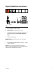
Nipple Installation Instructions C B A FIG. 4 A B C M8x1 connection for fitting + sleeve Copper Washer M10 x 1 or M12 x 1 straight fitting for dosers 1. (If adding nipple to casting with red or white plug, or replacing an existing nipple) Relieve pressure, page 7. 2. Carefully remove cap. NOTE: Due to spring located under cap, cap will be under pressure. 3. Thread nipple into fitting. Torque to 13 to 17. 7 in-lbs (1.46 to 1.99 N.m). NOTE: For a #1 nipple only, piston must also be removed.
Technical Data Technical Data Oil Lubricant Working pressure Pressure relief Working temperature Gasket material Viscosity Synthetic and mineral oils 145 to 652 psi (10 to 45 bar, 1.0 to 4.5 MPa) < 21.7 psi(1.5 bar, 0.15 MPa) 32° to 158°F (0° to 70°C) FPM 1.25 to 78.3 inches 2 /sec (32 to 2000 mm2 /sec) Grease Lubricant Working pressure Pressure relief Working temperature Gasket material Synthetic and mineral oils; fluid grease NLGI 00-000 145 to 652 psi (10 to 45 bar, 1.0 to 4.5 MPa) < 21.7 psi (1.
Technical Data Single Point Manifold Dimensions NOTE: All dimensions are provided in Metric (mm) only. H H M B A E G D L N K F C FIG. 5 Fitting and Pipe Outlets Sleeve A B M10 x 1 C D 8 130 52 10 156 78 6 113 39 8 139 65 6 126 68 6 M14 x 1’5 8 6 M10 x 1 A E F G H K L M N Material 17 13 10’5 13 2.8 7.4 4’3 4 Aluminum 20 18 11 13 2.8 7.4 4’3 4 Aluminum 20 18 11 17 2.8 7.4 4’3 4 Aluminum B H F G E K D J C FIG. 6 313759A Part No.
Technical Data 12 15X670 M10 / M8 18 5 100 88 25.4 15 18 16 7.5 6 15X671 M10 / M8 18 6 116 104 25.4 15 18 16 7.5 6 15X672 M10 / M8 18 7 132 120 25.4 15 18 18 7.5 6 15X673 M10 / M8 18 8 148 136 25.4 15 18 18 7.5 6 15X674 M10 / M8 18 10 180 168 25.4 15 18 18 7.5 6 15X675 M10 / M10 18 2 54 42 25.4 15 18 18 7.5 6 15X676 M10 / M10 18 3 72 60 25.4 15 18 18 7.5 6 15X677 M10 / M10 18 4 90 78 25.4 15 18 18 7.
Technical Data Dimensions cc 2 Outlets 3 Outlets 5 Outlets A 5 5 J H G 5 5 5 K 4 5 5 5 4 5 dd 3 5 5 5 4 5 3 2 5 1 aa bb F C E B M N D D B B FIG. 7 Model 3500/3510 Mounting Hole Locations (see note with dd). 6 5 5 dd 6 4 5 5 6 4 5 5 3 5 6 7 3 5 2 5 1 dd FIG. 8 aa bb cc dd Flow Index Outlet Number Pipe = Ø4 Mounting Hole Location: NOTE: 3400, 3410, 3900 and 3910 Models. For Model 3500 and 3510 mounting hole locations see FIG. 8,.
Technical Data Dimensions (All models)* Ref. 3400 / 3410 3500 / 3510 3900 / 3910 Outlets 2 3 5 2 3 5 2 3 A .67 in. (17 mm) .67 in. (17 mm) .67 in. (17 mm) .67 in. (17 mm) .67 in. (17 mm) .67 in. (17 mm) .82 in. (21 mm) .82 in. (21 mm) B 1.9 in. (48 mm) 2.55 in (65 mm) 3.9 in. (99 mm) 1.81 in. (46 mm) 2.48 in. (63 mm) 3.8 in. (97 mm) 1.96 in. (50 mm) 2.8 in. (71 mm) C .94 in. (24 mm) .94 in. (24 mm) .94 in. (24 mm) .90 in. (23 mm) 1.24 in. (31.5 mm) 1.9 in. (48.5 mm) .
Technical Data Single Point Oil 3400 3500 REF Description 3900 A D 3900 4 mm 4mm 4mm 1.7 in. (43.5 mm). 2.7 in. (67.5 mm) 2.6 in. (66.5 mm) Outlet Pipe Connection B Height C Connection depth .236 in. (6 mm) .256 in. (6.5 mm) .315 in. (8 mm) Width .472 in. (12 mm) .630 in. 16 mm) .827 in. (21 mm) D B 3500 A D B 3400 B D C C C FIG. 9 Single Point Grease (NLGI 00-000) 3410 3910 3510 A Ref A 4 6 6 B D B C D C Models 3410 3510 3910 4 mm 4 mm 4 mm 1.81 in.
Technical Data Piston Distributors Type F A B C D E F G J C B H G 3 A F E D K L FIG. 11 10 Flow Index M14 x 1.5 40.6 32.5 23.5 Ø11.7 Housing H 17 J M14 x 1.5 K 15 L 35 Type GC B E 3 A C FIG. 12 16 G D F H A B C D E 13.5 10 M3 50 Flow Index Housing F 13.
Notes Notes 313759A 17
Graco Standard Warranty Graco warrants all equipment referenced in this document which is manufactured by Graco and bearing its name to be free from defects in material and workmanship on the date of sale to the original purchaser for use. With the exception of any special, extended, or limited warranty published by Graco, Graco will, for a period of twelve months from the date of sale, repair or replace any part of the equipment determined by Graco to be defective.