Operation ThermoLazer™ Pavement Marking System 313787C US Patent No. D619,625 S ENG - For professional application of thermoplastic traffic marking compound materials (reflective beads applied simultaneously with screeding) - For outdoor use only (not to be operated in rain or damp conditions) Model No. 258699 North America - Includes 257500 and 4 in. (10 cm) SmartDie™ Screed Box Model No.
Table of Contents Table of Contents Table of Contents . . . . . . . . . . . . . . . . . . . . . . . . . . 2 Warnings . . . . . . . . . . . . . . . . . . . . . . . . . . . . . . . . . 3 Component Identification . . . . . . . . . . . . . . . . . . . . 5 Component ID (Continued) . . . . . . . . . . . . . . . . . . . 6 Important Safety Information . . . . . . . . . . . . . . . . . 7 Lighting Instructions . . . . . . . . . . . . . . . . . . . . . . . 10 SmartDie™ Screed Box . . . . . . . . . . . . . . . . . . .
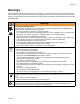
Warnings Warnings The following are general warnings related to the safe setup, use, grounding, maintenance and repair of this equipment. In the text of this manual, the exclamation point symbol alerts you to a warning and the hazard symbol refers to specific risks. Refer back to these General Warnings pages. Additional procedure-specific warnings will be included where applicable.
Warnings Warnings TOXIC FLUID OR FUMES HAZARD Toxic fluids or fumes can cause serious injury or death if splashed in the eyes or on skin, inhaled, or swallowed. • Read MSDS to know the specific hazards of the materials you are using. PERSONAL PROTECTIVE EQUIPMENT You must wear appropriate protective equipment when operating, servicing, or when in the operating area of the equipment to help protect you from serious injury, including eye injury, inhalation of toxic fumes, burns, and hearing loss.
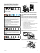
Component Identification Component Identification U N X S P Z W Y A L C R AB J M U ti14145a V T K H A Kettle Main Burners R ControlFlow™ Gate Valve C Kettle Pilot Burner S ControlFlow™ Gate Valve Actuator H Line Guide T SmoothRide™ Swivel Tire U Lock/Unlock for Swivel Wheel J LP Gas Cylinder Holder K SmartDie™ Lever V Kettle Pilot Ignitor Electrode L Kettle Thermopile W Central Pour Access Cover with Latches M Bead Dispenser Box X N ™ PaddleMax™ Agitator Actuator Y
Component ID (Continued) Component ID (Continued) LL AA JJ BB HH KK GG DD ti14146a EE CC Ref.
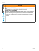
Important Safety Information Important Safety Information If you do not follow these instructions exactly, a fire or explosion may result causing property damage, personal injury or death. Keep gas supply hose away from hot surfaces and flames. Use equipment in accordance with state and local ordinances with Storage, Handling and Transportation of Liquid Petroleum Gases, ANSI/NFPA58 or CSA B149.1 If equipment has been in storage, check for insects and insect nests on burners and Venturi tubes.
Important Safety Information Important Safety Information WHAT TO DO IF YOU SMELL GAS OR FIND GAS BUBBLES: • Evacuate all unqualified personnel from area If you do not follow these instructions exactly, a fire or explosion may result causing property damage, personal injury or death. BEFORE LIGHTING: Smell all around the working area for gas. Be sure to smell next to the ground because propane is heavier than air and will settle on the ground. DAILY: Check for gas leaks.
Important Safety Information Important Safety Information Before attempting to start equipment: If you do not follow these instructions exactly, a fire or explosion may result causing property damage, personal injury or death. ti14409a DAILY: Check all gas lines and fittings for gas leaks. DAILY: Check gas supply hose for wear, abrasions, cuts or leaks. Replace only with hoses recommended by Graco. All surfaces are capable of becoming extremely hot.
Lighting Instructions Lighting Instructions Lighting Kettle Burners 6. Push in gas safety valve knob. 7. Push kettle pilot burner igniter (DD) until pilot ignites. 8. Continue to push in gas safety valve (CC) in for approximately 1 minute. If pilot goes out, repeat steps 4-6 after 10 minutes. Read For Your Safety, page 7. 1. Turn temperature control knob (AA) to 0 (“OFF”). If pilot ignites without depressing the gas safety valve knob, replace gas safety valve.
Lighting Instructions Torch Lighting Instructions Shutting Off Torch 1. Fully close torch flame adjusting valve. 1. Open manual shut-off valve on propane tank located at front of unit. ti14605a ti14127a 2. Open torch manual shut-off valve next to torch regulator. 2. Close torch manual shut-off valve when finished heating with torch. ti14137a 3. Remove external torch from holder. ti14602a 3. Close manual shut-off valve on propane tank when finished heating with torch. ti14138a ti14128a 4.
Lighting Instructions SmartDie™ Screed Box IR Burner Lighting Instructions 5. Place torch at end of IR burner next to stainless steel mesh on burner. Read Important Safety Information, page 7. 1. Open manual shut-off valve on propane tank located at front of unit. ti14142a 6. Press in safety shut-off valve knob (HH). ti14127a 2. Light torch (see Torch Lighting Instructions, page 11). 3. Turn gas flow control knob (JJ) to full-on (three flames position). JJ HH ti14143a 7.
SmartDie™ Screed Box SmartDie™ Screed Box Installation 5. Engage SmartDie™ screed box rod into SmartDie™ lever. Use extreme caution when installing and removing screed box. Expect all equipment components and material to be extremely hot. See MSDS for Thermoplastic Traffic Marking Compound. 1. Shut off the SmartDie™ screed box IR burner. ti14268a 6. Align hole of rod clevis with connecting hole in SmartDie™ screed box yoke and install hairpin cotter pin. ti14126a ti14155a 2. Open screed shroud door.
SmartDie™ Screed Box 3. Set SmartDie™ screed box on ground but not in locked open position. 1. Loosen two bolts on SmartDie™ screed box mounting bracket. ti14504a ti14267a 4. Remove hairpin cotter pin connecting SmartDie™ screed box to rod clevis. 2. Slide mount down until leading box edge of SmartDie™ screed box die runner is just off of the ground surface. For best performance, raise leading edge 0 - 0.03 in. (0 - 0.076 cm) off ground surface. ti14155a ti14505a 5. Press down SmartDie™ lever.
SmartDie™ Screed Box Replacing SmartDie™ Screed Box Spring 1. Position replacement spring as shown below and slide into spring guard. 4. Loop open end of spring and guard over first pin on SmartDie™ screed box. Then push spring guard up and over second pin on SmartDie™ screed box. ti14551a 2. Push spring up through guard and loop end around guard pin until spring sits in groove. ti14552a ti14550a NOTE: Make sure spring end is fully engaged in groove to prevent spring from coming loose.
Preparing ThermoLazer™ for Application Preparing ThermoLazer™ for Application 5. Move ControlFlow™ Gate Valve Actuator (S) to raised position and fill screed box with melted thermoplastic material. Keep all access covers closed and latched when equipment is in use. Always secure ThermoLazer™ by chocking wheels when adding thermoplastic. S 1. Make sure kettle burners and SmartDie™ screed box burner are lit. 2. Allow kettle to heat up before adding material.
Bead Dispenser Box Bead Dispenser Box The Bead Dispenser Box has three doors which can be opened and closed to allow beads to be dispensed at desired width patterns. ti14153a ti14151a Bead flow rate can be adjusted using the Bead Flow Rate Lever on the outside of the Bead Dispenser Box. ti14152a ti14157a Adding Beads to SplitBead™ Bead Hopper Single Bead Application Bead Dispenser Engagement Wheel 1. Unlock and open SplitBead™ bead hopper door.
Shutting Down Shutting Down 5. Turn torch gas flow valve to closed position. 1. Turn kettle gas safety valve (CC) to “OFF” position. ti14139a ti14626a 6. Turn torch manual shut-off valve OFF. 2. Turn temperature control knob (AA) to 0 (“OFF”). ti14124a 7. Turn main gas valve on propane tank OFF. 3. Turn screed burner regulator/flow control valve to “0” (OFF). ti14128a ti14126a 4. Close kettle burner manual shut-off valve (KK) below kettle and behind propane tank OFF.
Clean-Up Clean-Up NOTICE Never scoop out remaining melted thermoplastic from kettle. Remaining thermoplastic can be left to harden inside the kettle and can be remelted at a later date. Always secure ThermoLazer™ by chocking wheels when adding thermoplastic. 1. Secure ThermoLazer™ by chocking wheels. Be sure to thoroughly clean all material on BlackMax™ Screed Die bar of screed box and any open areas to prevent material from freezing moving parts of screed box.
Maintenance Maintenance DAILY: Make sure kettle main burners (A) are burning correctly. The flame should be 1 - 2 in. (2.5 - 5.0 cm) high and blue/orange in color. 1 to 2 in. DAILY: Check gas lines and fittings for gas leaks. Use soap and water mixture or LP-gas leak detector to detect gas leaks. A DAILY: Check LP-gas supply hose for abrasions, cut or wear. Make sure hose fitting and tank fitting are free of debris before connecting. DAILY: Make sure kettle gas safety valve (CC) rotates freely.
Maintenance Fat Track™ Front Swivel Wheel System FatTrack™ Front Swivel Tire Alignment ANNUALLY: Tighten nut (86a) on screw under dust cap (92) until spring washer bottoms out. Then back off the nut 1/2 to 3/4 turns. 1. Loosen cap screw (86h). Align front wheel as follows: ANNUALLY: Tighten nut (82) on screw (90) until it begins to compress spring washer (83). Then tighten an additional 1/4 turn. 86h MONTHLY: Grease the wheel bearing. PERIODICALLY: Check caster locking pin (86t) for wear.
Technical Data Technical Data Fuel: Gas supply pressure (maximum): Kettle burner inlet pressure: IR burner inlet pressure: Torch inlet pressure: Kettle main burner heating capacity (maximum): Kettle pilot burner heating capacity (maximum): IR burner heating capacity (maximum): Torch heating capacity (maximum): Kettle holding capacity (maximum): Kettle Temperature (maximum): Kettle Temperature (operating): Tire pressure (rear wheels): Tire pressure (swivel wheel): Battery (Kettle Pilot Burner Igniter): Bead
Notes Notes 313787C 23
Graco Standard Warranty Graco warrants all equipment referenced in this document which is manufactured by Graco and bearing its name to be free from defects in material and workmanship on the date of sale to the original purchaser for use. With the exception of any special, extended, or limited warranty published by Graco, Graco will, for a period of twelve months from the date of sale, repair or replace any part of the equipment determined by Graco to be defective.