Instructions Injecto-Flo II Single Line Pumps with No Control 313839C EN - For feeding volumetric dosing meters in a single-line system - Not for use in hazardous locations - Part No.: See page 2 OIL: 435 psi (3.0 MPa, 30 bar) Maximum Working Pressure GREASE: 580 psi (4.0 MPa, 40 bar) Maximum Working Pressure Important Safety Instructions Read all warnings and instructions in this manual. Save these instructions.
Models Models Oil Systems Model CE Reservoir Gal (liters) Flow GPM (lpm) Level Switch 122545 ✓ 0.8 (3.0) 0.05 (0.2) None Screw Cap 122546 ✓ 0.8 (3.0) 0.05 (0.2) None Straight Connector (∅ 10 pipe) 122547 ✓ 0.8 (3.0) 0.13 (0.5) None Screw Cap 122548 ✓ 0.8 (3.0) 0.13 (0.5) None Straight Connector (∅ 10 pipe) 122549 ✓ 0.8 (3.0) 0.05 (0.2) Single w/DIN Screw Cap 122550 ✓ 0.8 (3.0) 0.05 (0.2) Single w/DIN Straight Connector (∅ 10 pipe) 122551 ✓ 0.8 (3.0) 0.13 (0.
Models Model CE Reservoir Gal (liters) Flow GPM (lpm) Level Switch 122574 ✓ 1.6 (6.0) 0.05 (0.2) Dual w/DIN Screw Cap 122575 ✓ 1.6 (6.0) 0.05 (0.2) Dual w/DIN Straight Connector (∅ 10 pipe) 122576 ✓ 1.6 (6.0) 0.13 (0.5) Dual w/DIN Screw Cap 122577 ✓ 1.6 (6.0) 0.13 (0.5) Dual w/DIN Straight Connector (∅ 10 pipe) 122578 ✓ 1.6 (6.0) 0.05 (0.2) Dual w/M12 Top Screw Cap 122579 ✓ 1.6 (6.0) 0.05 (0.2) Dual w/M12 Top Straight Connector (∅ 10 pipe) 122580 ✓ 1.6 (6.0) 0.
Warnings Warnings The following warnings are for the setup, use, grounding, maintenance, and repair of this equipment. The exclamation point symbol alerts you to a general warning and the hazard symbol refers to procedure-specific risk. Refer back to these warnings. Additional, product-specific warnings may be found throughout the body of this manual where applicable.
Warnings Grounding The equipment must be grounded. Grounding reduces the risk of static and electric shock by providing an escape wire for the electrical current due to static build up or in the event of a short circuit. Pressure Relief Procedure To relieve pressure, loosen outlet fitting connection to bleed air and relieve pressure. NOTE: Pumps have a built-in decompression valve that relieves pressure when cycle is complete.
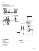
Installation Installation Component Identification Doser B Hydraulic Diagram G D H F Doser C J G D E A B C A FIG.
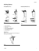
Installation Refilling Options Oil Systems (FIG. 2) Grease Systems (FIG. 3) A A B C D B C E D F F H C G C G FIG. 2 FIG. 3 A B C D E F G Screw Cap Option Elbow Connector Option Screw Cap Strainer Basket (Oil Models Only) Down Tube (Oil Models Only) Vent (additional information) Elbow Connector Vent (FIG. 4) NOTE: A vent is included with all units with refilling systems using a connector (G). F FIG.
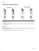
Installation Level Switch Connector Options Grease Systems Oil Systems A B A B FIG. 5 A Standard Connector Option: Minimal level with standard DIN connector; Minimum + Prealarm level with standard DIN connector. B M12 Connector Top Entry Option: Minimum level with M12 connector top entry; Minimum + Premalarm level with M12 connector top entry. Instructions The control of these units is external (without control) programming by the machine automatism or external control (CNC, Automatic device, etc.
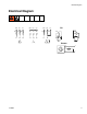
Electrical Diagram Electrical Diagram W 2 U2 U1 V1 V2 W1 W 2 U2 V2 V1 W1 U1 W 2 U2 U1 V1 Oil V2 W1 MIN. MIN. PRE.
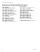
Replacement Parts Available from Graco Replacement Parts Available from Graco Part No. 122901 122902 122903 122904 122905 122906 122907 122908 122909 122910 122911 122912 122913 122914 122915 122916 122917 122918 122919 122920 10 Description PUMP, electric motor, oil, 0.2L/min PUMP, electric motor, oil, 0.
Technical Data Technical Data Tank Capacity Models: Oil . . . . . . . . . . . . . . . . . . . . . . . . . . . . . . . . . Models: Grease . . . . . . . . . . . . . . . . . . . . . . . . . . . . . Tank Material. . . . . . . . . . . . . . . . . . . . . . . . . . . . . . . . . . Output Connection . . . . . . . . . . . . . . . . . . . . . . . . . . . . . Pump Lubricant Models: Oil . . . . . . . . . . . . . . . . . . . . . . . . . . . . . . . . . Models: Grease . . . . . . . . . . . . . . . . . . . . . . . . . .
Technical Data Dimensions 5.37 in. (136.5 mm) _ 11.3 in. (289 mm) 6 in. (152.5 mm) 5.59 in (142 mm) 8.6 & 9.0 in. (220 & 230 mm) 9.65 in.
Notes Notes 313839C 13
Graco Standard Warranty Graco warrants all equipment referenced in this document which is manufactured by Graco and bearing its name to be free from defects in material and workmanship on the date of sale to the original purchaser for use. With the exception of any special, extended, or limited warranty published by Graco, Graco will, for a period of twelve months from the date of sale, repair or replace any part of the equipment determined by Graco to be defective.