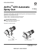
Instructions/Parts AirPro™ EFX Automatic Spray Gun 313869K EN Conventional, HVLP, HiTEch, and LVMP automatic guns for small component finishing applications. For professional use only. 100 psi (0.7 MPa, 7 bar) Maximum Working Fluid Pressure 100 psi (0.7 MPa, 7 bar) Maximum Working Air Pressure Important Safety Instructions Read all warnings and instructions in this manual. Save these instructions. See page 3 for model information.
Contents Models . . . . . . . . . . . . . . . . . . . . . . . . . . . . . . . . . . . 3 Warnings . . . . . . . . . . . . . . . . . . . . . . . . . . . . . . . . . 4 Selection Charts . . . . . . . . . . . . . . . . . . . . . . . . . . . 8 Gun Selection . . . . . . . . . . . . . . . . . . . . . . . . . . . 8 Proper Needle/Nozzle Selection . . . . . . . . . . . . . 8 Models With Manifolds . . . . . . . . . . . . . . . . . . . . 9 Models Without Manifolds . . . . . . . . . . . . . . . . . 10 Air Caps . . . . .
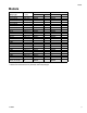
Models Models Orifice Size in. (mm) Models with Manifold** Spray Type Gun Part No. Series Conventional 0.028 (0.7) 24B857 C Conventional 0.035 (0.9) 24B858 C Conventional 0.039 (1.0) 24M390* A Conventional 0.043 (1.1) 24B859 C Conventional 0.051 (1.3) 24B860 C Conventional 0.059 (1.5) 24B861* C HVLP 0.020 (0.5) 24B862 C HVLP 0.028 (0.7) 24B863 C HVLP 0.043 (1.1) 24B864 C HVLP 0.051 (1.3) 24B865 C HiTEch 0.028 (0.7) 24B866 C HiTEch 0.039 (1.0) 24B867* C HiTEch 0.059 (1.5) 24B868* C LVMP 0.020 (0.
Warnings Warnings The following warnings are for the setup, use, grounding, maintenance, and repair of this equipment. The exclamation point symbol alerts you to a general warning and the hazard symbols refer to procedure-specific risks. When these symbols appear in the body of this manual or on warning labels, refer back to these Warnings. Product-specific hazard symbols and warnings not covered in this section may appear throughout the body of this manual where applicable.
Warnings WARNING EQUIPMENT MISUSE HAZARD Misuse can cause death or serious injury. • • • • • • • • • • • Do not operate the unit when fatigued or under the influence of drugs or alcohol. Do not exceed the maximum working pressure or temperature rating of the lowest rated system component. See Technical Data in all equipment manuals. Use fluids and solvents that are compatible with equipment wetted parts. See Technical Data in all equipment manuals. Read fluid and solvent manufacturer’s warnings.
Warnings WARNING TOXIC FLUID OR FUMES HAZARD Toxic fluids or fumes can cause serious injury or death if splashed in the eyes or on skin, inhaled, or swallowed. Read MSDSs to know the specific hazards of the fluids you are using. • Store hazardous fluid in approved containers, and dispose of it according to applicable guidelines.
Warnings 313869K 7
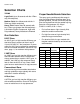
Selection Charts Selection Charts TERMS Proper Needle/Nozzle Selection Light Fluid: Up to 18 seconds with No. 2 Zahn cup (20 centipoise) The spray gun's needle/nozzle kits range in size to provide different fluid flow rates. As a general guideline, use the fluid nozzle that will give the required flow with the needle fully triggered at a fluid pressure of 5–20 psi (0.035–0.14 MPa, 0.35–1.4 bar). Medium Fluid:19 to 28 seconds with No.
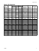
Selection Charts Models With Manifolds Gun Assembly Part No. 24B857 24B858 24M390 24B859 24B860 24B861 24B862 24B863 24B864 24B865 24B866 24B867 24B868 24B869 24B870 24B871 24M391 24P993 24B872 24B873 24P994 24B874 24B875 24B876 313869K Type Conventional Conventional Conventional Conventional Conventional Conventional HVLP HVLP HVLP HVLP HiTEch HiTEch HiTEch LVMP LVMP LVMP LVMP LVMP LVMP LVMP LVMP LVMP Air Brush N/A Includes: Needle/ Air Cap Nozzle Kit with Pin Part No. Part No.
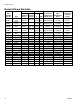
Selection Charts Models Without Manifolds Gun Assembly Part No. 24B877 24B878 24M392 24B879 24B880 24B881 24B882 24B883 24B884 24B885 24B886 24B887 24B888 24B889 24M393 24P995 24B890 24B891 24P996 24B892 24B893 10 Type Conventional Conventional Conventional Conventional Conventional HVLP HVLP HVLP HiTEch HiTEch HiTEch LVMP LVMP LVMP LVMP LVMP LVMP LVMP LVMP Air Brush N/A Includes: Needle/ Air Cap Nozzle Kit with Pin Part No. Part No.
Selection Charts Air Caps Nozzle Orifice Air Cap Part No. 24C182 24C183 24D703 24D704 24C184 24D705 * Type Conventional HVLP HiTEch HiTEch LVMP Air Brush Recommended Gun/Manifold Inlet Pressure in. mm. psi (MPa, bar) 0.028-0.059 0.7-1.5 43 (0.3, 3.0) 0.020-0.051 0.5-1.3 15 (0.1, 1.0)* 0.028-0.039 0.7-1.0 29 (0.2, 2.0) 0.059 1.5 29 (0.2, 2.0) 0.020-0.059 0.5-1.5 43 (0.3, 3.0) 0.028 0.7 29 (0.2, 2.0) Air Cap Color Blue-Grey Pewter Black Black Brown Clear Maximum compliant HVLP inlet pressure.
Installation Installation This spray gun can spray most coatings or finishes currently being used for small component plastic, wood and metal finishing applications, while easily operating from paint delivery systems, such as pressure pots or remote pumps for production line operation. The air regulator must have a minimum air flow capacity of 30 scfm at 100 psi (0.7 MPa, 7.0 bar) air pressure. Ventilate Spray Booth Configure Gun and Manifold Guns with Manifold See FIG. 1.
Installation Guns without Manifold Pump/Fluid Supply The gun is shipped ready for use in a circulating system, with a fitting installed in each fluid port. Connect the fluid supply line to one fluid inlet fitting (15) and the fluid return line to the other. Ground the pump by connecting a ground wire and clamp between the fluid supply and a true earth ground as instructed in your separate pump instruction manual.
Installation Mount Gun Reciprocating Arm Rod Mount To mount the gun on a reciprocating arm rod [0.75 in. (19 mm) diameter maximum], insert the bar (A) through the hole in the manifold as shown in FIG. 3. NOTE: Use the 1/8 in. alignment slot (P) to assist in orienting the gun. Secure the gun to the bar by tightening the mounting screw (B). C Guns with manifold TI14434A C A B P TI14433A FIG. 3: Reciprocating Arm Mount Stationary Support To mount the gun on a stationary support, refer to FIG.
Setup Setup Connect Air Line NOTE: • • • If your regulated air source does not have a filter, install an air filter (G) on each air line to ensure a dry, clean air supply to the gun. Dirt and moisture can ruin the appearance of your finished workpiece. See FIG. 5. You must install a separate air pressure regulator (F) on the CYL, FAN, and ATOM air lines to control air pressure to the gun. See FIG. 6 and FIG. 7.
Setup Air regulator ATOMIZING AIR 2-way solenoid valve CYLINDER AIR 3-way solenoid valve FAN AIR 2-way solenoid valve TI14444A FIG. 6: Remote Air Regulation using Solenoid (Guns with Manifold) FAN AIR 2-way solenoid valve CYLINDER AIR 3-way solenoid valve ATOMIZING AIR TI14445A 2-way solenoid valve FIG.
Setup Connect Fluid Hose NOTE: Before connecting the fluid line, blow it out with air and flush it with solvent. Use solvent that is compatible with the fluid to be sprayed. Install a fluid regulator (L) on the fluid line to control fluid pressure to the gun. See FIG. 8. Install a fluid shutoff valve (M) to shut off the fluid supply to the gun. Filter the fluid line of coarse particles and sediment to avoid clogging the fluid nozzle and causing finishing defects. Inline fluid filter 24B707 is available.
Setup Flush Spray Gun Adjust Spray Pattern Before running any paint through the spray gun: Do not exceed 100 psi (0.7 MPa, 7 bar) maximum fluid and air pressure. Higher pressures can cause parts to rupture and result in serious injury. 1. Flush the gun with a solvent that is compatible with the fluid to be sprayed, using the lowest possible fluid pressure and a grounded metal container. See Clean and Flush Gun, page 22. 2. Perform Pressure Relief Procedure, page 20.
Setup NOTE: HVLP Gun Limits HVLP Guns: local laws may limit the maximum pressure to 10 psi (70 kPa, 0.7 bar) at the air cap for compliance. See the table on page 11 for maximum HVLP manifold inlet pressures. To measure pressure at the air cap, use the appropriate HVLP Pressure Verification Kit. L ti7019a FIG. 11: Fluid Pressure Regulator NOTE: A larger fluid nozzle at a reduced fluid pressure will maintain the same flow rate, but the fluid stream (velocity) will slow down.
Operation Operation Pressure Relief Procedure 1. Turn off all bleed type air valves and all other air and fluid supplies to the gun. 2. Trigger the gun into a grounded metal waste container to relieve fluid pressure. To achieve best results when applying fluid: • Keep gun perpendicular and 6 to 8 in. (150 to 200 mm) from object being sprayed. • Use smooth, parallel strokes across surface to be sprayed with 50% overlap. Incorrect TI14439A ti8174a FIG.
Operation Daily Gun Care NOTICE Methylene chloride with formic or propionic acid is not recommended as a flushing or cleaning solvent with this gun as it will damage aluminum and nylon components. NOTICE Solvent left in gun air passages could result in a poor quality paint finish. Do not use any cleaning method which may allow solvent into the gun air passages. Do not point the gun up while cleaning it. Do not wipe the gun with a cloth soaked in solvent; wring out the excess.
Operation General System Maintenance • Follow the Pressure Relief Procedure, page 20. • Clean the fluid and air line filters daily. • Check for any fluid leakage from the gun and fluid hoses. Tighten fittings or replace equipment as needed. • Flush the gun before changing colors and whenever you are done operating the gun. 9. Dip the end of a soft-bristle brush into a compatible solvent. Do not continuously soak the brush's bristles with solvent and do not use a wire brush.
Operation 313869K 23
Troubleshooting Troubleshooting Problem Spray Pattern Cause Solution Normal pattern. No action necessary. Dirty or damaged air cap or fluid nozzle. Rotate air cap (5) 180°. Right Spray Pattern If pattern follows air cap, problem is in air cap. Clean and inspect. If pattern is not corrected, replace air cap. Wrong Heavy top or bottom Spray Pattern Fan pressure too high for viscosity of material being sprayed. If pattern does not follow the air cap, the problem is with the fluid nozzle (4).
Troubleshooting Problem Gun spitting. Cause Air getting into paint stream. Solution Check if fluid source is empty and fill. Tighten fluid nozzle (4). Check fluid nozzle o-ring (3) for damage. Will not spray. Excessive air blowing back. Gun fluid pressure is too high with gun triggered (cannot achieve desired flow rate). Using a low fluid pressure setting, the fluid flow is too high, making it necessary to restrict needle travel to reduce fluid flow.
Service Service screws (16) and remove the gun from the manifold. NOTE: Numbers in parenthesis in the text refer to the reference numbers in the figures and in the parts list. b. Without Manifold: Disconnect the air and fluid hoses. Remove the gun from the mounting arm. 3. Remove the air cap retaining ring (21) and air cap (5). Disassembly 1. Follow the Pressure Relief Procedure, page 20. 2. Remove gun for service: a. With Manifold: Use the 4 mm allen wrench supplied to unscrew the two 4.
Service 6. Use a 1/16 hex wrench to loosen the fluid needle set screw (7a). Remove the needle (6) from the piston (7). 7 1 6 7a 7. Check the fluid needle (6) for damage or excessive wear. Replace the needle if necessary. NOTICE The needle and tip are permanently bonded. To prevent damage to the needle, do not try to separate. 8. Use the 10 mm hex nut driver to remove the fluid packing nut (2). 9. Use the 10 mm wrench to remove the nozzle (4). Reassembly ti14944a 1 Torque to 4.5 to 5.5 in-lb (0.
Parts Parts 7 7b 16 1 7a 6 Guns with Manifold 2 Ultra-precision knob 3 Indexing knob 4 5d 5a 13 Lock ring and cap 11 20 13 10 20 14 5b 18 15 5c 21 12 19 ti14447a 17 ti14945a 7a Guns without Manifold 15 1 11 2 10 7 4 7b 3 6 5d 5a 5b 5c 21 15 14 ti14448a 28 313869K
Parts Parts in Common Ref. Part 1 2 3 4 5 ----24C205 119348 See Table See Table Description BODY FLUID PACKING ASSEMBLY O-RING (included with Part 4) NOZZLE, fluid (includes Part 3) AIR CAP ASSEMBLY (includes Parts 5a-5d) 5a ----AIR CAP 5b✓ ----O-RING 5c✓ ----WASHER, UMHWPE 5d ----PIN, alignment 6 See Table NEEDLE assembly 7 24C202 PISTON, needle stop (includes Parts 7a and 7b) 7a ----SCREW, set, 6-32 UNC x 1/16 in.
Repair Kits Repair Kits Gun Part Number Spray Type Conventional Conventional Conventional Conventional Conventional Conventional HVLP HVLP HVLP HVLP HiTEch HiTEch HiTEch LVMP LVMP LVMP LVMP LVMP LVMP LVMP LVMP LVMP Air Brush With Manifold 24B857 24B858 24M390* 24B859 24B860 24B861* 24B862 24B863 24B864 24B865 24B866 24B867* 24B868* 24B869 24B870 24B871 24M391* 24P993 24B872 24B873 24P994 24B874* 24B875 Without Manifold 24B877 24B878 24M392* 24B879 24B880 --------24B881 24B882 24B883 24B884 24B885* 24B88
Accessories Accessories Kit 24C216, Fittings (1/4 inch) Part Description 120388 FITTING, tube, air line, 1/8 npt x 1/4 T 111157 FITTING, tube, fluid line, 1/8 npt x 1/4 T Qty . 3 2 Kit 24D143, Robot Adapter Kit Fanuc Paint Mate 200 Compatible with and without manifold. Kit 24D008, Inlet Air Needle Valve Includes needle valve and 6mm tube fittings. Kit 24D827, Manifold O-Rings Part Description 106456 O-RING, PTFE, white 112319 O-RING, FX75, black Qty .
Accessories 32 313869K
Dimensions Dimensions Guns with Manifold 1.6 in. (40.7 mm) 4.9 in. (124.5 mm) with Ultra-Precision knob 4.1 in. (104.1 mm) with indexing knob 3.5 in. (88.9 mm) with lock ring and cap 1.3 in. (33.0 mm) 2.6 in. (66.1 mm) 1.4 in. (35.6 mm) 0.75 in. (19.1 mm) mounting hole 3.8 in. (96.5 mm) TI14436A TI14440A FIG. 20 Guns without Manifold 4.9 in. (124.5 mm) with Ultra-Precision knob 4.1 in. (104.1 mm) with indexing knob 3.5 in. (88.9 mm) with lock ring and cap 3.5 in. (88.9 mm) 2.2 in. (55.
Mounting Hole Layouts Mounting Hole Layouts Guns with Manifold 0.95 in (24.1 mm) 1.27 in (32.3 mm) ti14700a 0.34 in. (8.6 mm) thru 1.4 in (35.6 mm) 0.43 in. (10.9 mm) 0.13 in. (3.3 mm) slot 3 x M8 x 1.25 0.86 in. (21.8 mm) ti14441a 1.22 in. (31.0 mm) FIG.
Mounting Hole Layouts Guns without Manifold 1.76 in. (44.7 mm) M8 x 1.25 T 0.35 in. (8.9 mm) deep 0.95 in. (24.1 mm) 0.13 slot (3.3 mm) ti14701a FIG.
Technical Data Technical Data Maximum working fluid pressure Maximum working air pressure Maximum HVLP Inbound Air Pressure Maximum Working Fluid Temperature Minimum Air Cylinder Actuation Pressure Weight with manifold . . . . . . . . . . . . . . . . . . . . . . . . . . . . . . . . with no manifold . . . . . . . . . . . . . . . . . . . . . . . . . . . . . Wetted Parts Models 24B857-24B860, 24B862-24B865, 24B869-24B873, 24B875, 24P993, 24P994. . . . . . . . 100 psi (0.7 MPa, 7 bar) 100 psi (0.
Technical Data Triggering Speed These values apply to a new gun with a 12 ft. (3.6 m), 1/4 in. (6.3 mm) OD cylinder air line and a 0.043 in. nozzle. These values will vary slightly with use and with variations in equipment. Cylinder Air Pressure Fluid Pressure Air Pressure psi (kPa, bar) psi (kPa, bar) psi (kPa, bar) msec to fully open msec to fully close 50 (0.35, 3.5) 50 (0.35, 3.5) 100 (0.7, 7.0) 48 84 Sound Data Conventional Measured at 43 psi (0.30 MPa, 3.
Air Flow Air Flow See the chart to determine air consumption. Add the air consumption values shown for the atomizing air and fan air to get the total air consumption. For example, air cap 24C182 with 35 psi inlet pressure uses 3.9 scfm atomizing air and 5.4 scfm fan air for a total of 9.3 scfm air consumption. Air Cap 24C182 (Conv.) 24C183 (HVLP) 24D703 24D704 (HiTEch) 38 Gun/Manifold Inlet Pressure psi (MPa, bar) 10 (0.07, 0.7) 15 (0.10, 1.0) 20 (0.14, 1.4) 25 (0.17, 1.7) 30 (0.21, 2.1) 35 (0.24, 2.
Air Flow Spray Pattern Test Report Every AirPro EFX gun must pass a spray pattern test. The test report is printed and shipped in the box with the gun. A sample is reproduced here, with explanatory notes. AirPro EFX Spray Pattern Test Report Width: the distance from one end of the pattern to the other along the spray pattern major axis. Height: The distance from one end of the pattern to the other along the spray pattern minor axis.
Graco Standard Warranty Graco warrants all equipment referenced in this document which is manufactured by Graco and bearing its name to be free from defects in material and workmanship on the date of sale to the original purchaser for use. With the exception of any special, extended, or limited warranty published by Graco, Graco will, for a period of twelve months from the date of sale, repair or replace any part of the equipment determined by Graco to be defective.