
User's Manual


System Configuration and Part Numbers
4 313882C
System Configuration and Part Numbers
Configurator Key
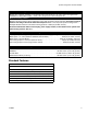
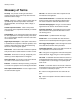
The configured part number for your equipment is printed on the equipment identification
labels. See F
IG. 1 for location of the identification labels. The part number includes digits from
each of the following categories, depending on the configuration of your system.
3K
System
Component C
Fluid Meter Component C Change
Not
Designated
Not
Designated
TK 0 = No Meter
1 = G3000
2 = G3000HR
3 = 1/8 in. Coriolis
4 = Solvent Meter
0 = No Valves (single component C)
1 = Two Valves (low pressure)
2 = Four Valves (low pressure)
3= Two Valves (high pressure)
4= Four Valves (high pressure)
00
FIG. 1: Identification Label
.7 7 100
MAX AIR WPR
MPa bar PSI
MAX FLUID WPR
MPa bar PSI
PART NO. SERIES
Read Instruction Manual
Warning: Substitution of components
may impair intrinsic safety.
SERIAL
ProMix
®
3KS
Electronic Proportioner
MAX TEMP 50°C (122°F)
Intrinsically Safe (IS) System. Install
per IS Control Drawing No. 258682.
EasyKey Interface IS Associated
Apparatus for use in non hazardous
location, with IS Connection to Smart
Fluid Plate IS
Apparatus for use in:
Class I, Division 1, Group D T3 C
Hazardous Locations
Intrinsically safe
equipment for Class I,
Div 1, Group D, T3
Ta = -20°C to 50°C
CUS
FM08ATEX0074
II 2 G
Ex ia IIA T3
GRACO INC.
P.O. Box 1441
Minneapolis, MN
55440 U.S.A.
MFG. YR.
Label Location on
Power Supply Module
Label Location
on Fluid Station
Maximum Fluid
Working Pressure
is listed here
Configured Part Number
TI14376a
TI14370aTI14361a