Operation ® ProMix 3KS 313885C EN Plural Component Proportioner Automatic system for proportional mixing of plural component coatings. For professional use only. Approved for use in explosive atmospheres (except the EasyKey and 3KS Power Supply Module). Important Safety Instructions Read all warnings and instructions in this manual. Save these instructions. See page 4 for model information, including maximum working pressure. Equipment approval labels are on page 3.
Contents Related Manuals . . . . . . . . . . . . . . . . . . . . . . . . . . . 3 Equipment Approvals . . . . . . . . . . . . . . . . . . . . . . . 3 System Configuration and Part Numbers . . . . . . . 4 Configurator Key . . . . . . . . . . . . . . . . . . . . . . . . . 4 Standard Features . . . . . . . . . . . . . . . . . . . . . . . 5 Accessories . . . . . . . . . . . . . . . . . . . . . . . . . . . . . . . 7 Warnings . . . . . . . . . . . . . . . . . . . . . . . . . . . . . . . . . 8 Glossary of Terms . .
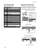
Related Manuals Related Manuals Equipment Approvals Component Manuals in English Equipment approvals appear on the following labels which are attached to the Fluid Station and Power Supply Module. See FIG. 1 on page 4 for label locations.
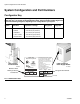
System Configuration and Part Numbers System Configuration and Part Numbers Configurator Key The configured part number for your equipment is printed on the equipment identification labels. See FIG. 1 for location of the identification labels. The part number includes digits from each of the following categories, depending on the configuration of your system.
System Configuration and Part Numbers Hazardous Location Approval Models using a G3000, G3000HR, or intrinsically safe Coriolis meter for A, B, and C meters are approved for installation in a Hazardous Location - Class I, Div I, Group D, T3 or Zone I Group IIA T3. Maximum Working Pressure Maximum working pressure rating is dependent on the fluid component options selected. The pressure rating is based on the rating of the lowest rated fluid component. Refer to the component pressure ratings below.
System Configuration and Part Numbers 6 313885C
Accessories Accessories Accessory Gun Flush Box Gun Insert Selection 15V354 Third Purge Valve Kit 15V536 Solvent Flow Switch Kit 15V213 Power Cable, 100 ft (30.5 m) 15G710 Fiber Optic Cable, 100 ft (30.
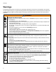
Warnings Warnings The following warnings are for the setup, use, grounding, maintenance, and repair of this equipment. The exclamation point symbol alerts you to a general warning and the hazard symbol refers to procedure-specific risk. Refer back to these warnings. Additional, product-specific warnings may be found throughout the body of this manual where applicable. WARNING FIRE AND EXPLOSION HAZARD Flammable fumes, such as solvent and paint fumes, in work area can ignite or explode.
Warnings WARNING EQUIPMENT MISUSE HAZARD Misuse can cause death or serious injury. • Do not operate the unit when fatigued or under the influence of drugs or alcohol. • Do not exceed the maximum working pressure or temperature rating of the lowest rated system component. See Technical Data in all equipment manuals. • Use fluids and solvents that are compatible with equipment wetted parts. See Technical Data in all equipment manuals. Read fluid and solvent manufacturer’s warnings.
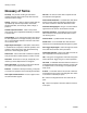
Glossary of Terms Glossary of Terms Air Chop - the process of mixing air and solvent together during the flush cycle to help clean the lines and reduce solvent usage. Analog - relating to, or being a device in which data are represented by continuously variable, measurable, physical quantities, such as length, width, voltage, or pressure. Closed Loop Flow Control - refers to the process when the flow rate is adjusted automatically to maintain a constant flow.
Glossary of Terms Manual Mode - when the proportioning or flow control system is controlling the inputs without any input from an outside control. Mix - when cross-linking of the resin (A), catalyst (B), and reducer (C) occurs. Mix Input Signal- refers to system mode status where system begins a dose sequence each time the mix signal is made “High”. Modbus/TCP - a type of communication protocol used to communicate Digital I/O signals over an ethernet.
Overview Overview Usage The Graco ProMix 3KS Kit adapts a ProMix 2KS system to be an electronic 3-component paint proportioner. It can blend most 3-component solvent and waterborne epoxy, polyurethane, and acid-catalyzed paints. It is not for use with “quick-setting” paints (those with a potlife of less than 15 minutes). • • • Can proportion at ratios from 0.1:1 to 50:1 in 0.1 increments with the wall mount fluid station.
Overview Component Description EasyKey (EK) Used to set up, display, operate, and monitor the system. The EasyKey accepts 85-250 VAC, 50/60 Hz line power and converts that power to acceptable low voltage and optical signals used by other system components. ★ 3KS Power Supply Module (PSM) Accepts 85-250 VAC, 50/60 Hz line power and converts that power to acceptable low voltage signals used by other system components.
Overview Component Flow Meters (MA, MB, ★MC, MS) Description Four optional flow meters are available from Graco: • G3000 is a general purpose gear meter typically used in flow ranges of 75-3800 cc/min. (0.02–1.0 gal/min.), pressures up to 4000 psi (28 MPa, 276 bar), and viscosities of 20–3000 centipoise. The K-factor is approximately 0.119 cc/pulse. • G3000HR is a high resolution version of the G3000 meter. It is typically used in flow ranges of 38–1900 cc/min. (0.01–0.5 gal/min.
Overview DVA DVB FI MB MS MA RVB RVA TI12556a APV AT SVA SM SVB SPV Key: ProMix 2KS Fluid Station MA Component A Meter DVA Component A Dose Valve RVA Component A Sampling Valve SVA Component A Shutoff Valve MB Component B Meter DVB Component B Dose Valve RVB Component B Sampling Valve DVC FI SVB Component B Shutoff Valve MS Solvent Meter SPV Solvent Purge Valve APV Air Purge Valve SM Static Mixer FI Fluid Integrator AT Air Purge Valve Air Supply Tube Key: ProMix 3KS Fluid Station MC CPV MC
EasyKey Display and Keyboard EasyKey Display and Keyboard Keypad LCD Display TI11630A Navigation Keys Alarm Reset Key FIG. 4. EasyKey Display and Keypad Display Shows graphical and text information related to setup and spray operations. Back light will turn off after 10 minutes without any key press. Press any key to turn back on. Keypad Used to input numerical data, enter setup screens, scroll through screens, and select setup values.
EasyKey and 3KS Power Supply Module Connection Ports EasyKey and 3KS Power Supply Module Connection Ports EasyKey Fiber Optic Strain Relief Port Audible Alarm AC Power Switch Main Power Access Port Ground Screw I/S Power to 2KS Panel Graco Web Interface Discrete I/O Cable Connector Ports TI12638a TI12657a 3KS Power Supply Module AC Power Switch Ground Screw Main Power Access Port I/S Power to 3KS Panel TI14366a TI14372a FIG. 5.
EasyKey and 3KS Power Supply Module Connection Ports EasyKey AC Power Switch Turns system AC power on or off. EasyKey Graco Web Interface Port Used to communicate from a PC to: 3KS Power Supply Module AC Power Switch Turns 3KS AC power on or off. EasyKey I/S Power Power circuit to 2KS Fluid Station. 3KS Power Supply Module I/S Power See manual 313386 for more information. Power circuit to 3KS Fluid Station. EasyKey Potlife Exceeded Audible Alarm Alerts the user when a Potlife Exceeded alarm occurs.
Run Mode Screens Run Mode Screens NOTE: See FIG. 8 for a map of the Run screens. Detailed screen descriptions follow. Splash Screen At power up, the Graco logo and software revision will display for approximately 5 seconds, followed by the Status Screen (see page 21). FIG. 6. Splash Screen The Splash screen will also momentarily display “Establishing Communication.
Run Mode Screens 1 / 4 Press the Setup key to enter Setup mode. 3 / 4 TI12802a FIG. 8.
Run Mode Screens Status Screen • 6 Potlife Timer: shows remaining potlife time in min- Use the Up or Down Run screens. keys to scroll through the utes. Two times are shown if there are two guns (manual or semi-automatic mode only). 7 Status Bar: shows current alarm or operation mode • Press the Setup key to enter the Setup screens (standby, mix, purge, recipe change, or the current alarm). from the Status screen. • The other keys have no function in this Status screen.
Run Mode Screens Manual Override Screen Flow Rate Range This screen displays the flow rate range selected on Advanced Setup Screen 5 (see page 37). Flow Set Point The Flow Set Point is user settable. If Flow Control Override is set to “Off” or “Pressure” in Advanced Setup Screen 1 on page 35, the Flow Set Point will display as cc/min. Enter the desired flow set point within the range. FIG. 10. Manual Override Screen If Flow Control Override is set to “% Open,” the Flow Set Point will display as % Open.
Run Mode Screens Reset Total Screen Global Flow Control Data Copy This field allows you to copy flow control data from the active recipe to all recipes. Press the Enter key to view the menu, then select Start or Abort. See FIG. 13. FIG. 15. Reset Total Screen FIG. 13. Global FC Data Copy If job is reset, job number will increment by one for default. Totals Screen Reset Solvent Screen 3 / 4 FIG. 14. Totals Screen FIG. 16.
Run Mode Screens Alarms Screens See FIG. 19. If the tank volume reaches the low-level threshold, the EasyKey screen will display the Tank Level Low alarm and prompt the user to do one of the following: 1. Refill tank volume to clear the alarm. 2. Resume mixing by selecting “Spray 25% of Remainder.” If this selection is chosen, a second alarm will occur after 25% of the remaining volume is mixed. Refill tank volume to clear the alarm. FIG. 17. Alarms Screen Two screens show the last 10 alarms.
Setup Mode Setup Mode Press the Setup key to enter Setup mode. NOTE: See FIG. 20 for a map of the Setup screens. Detailed screen descriptions follow. Press the Setup key to enter Setup mode. This screen appears only if a password is activated. To access Advanced Setup Screens, page 34 and Recipe Setup Screens, page 39. To access System Configuration Screens, page 28. Press the Setup key to exit Setup mode and return to the Status screen. This screen appears momentarily if a password is activated.
Setup Mode Password Screen Set Up Home Screen If a password has been activated (see Configure Screen 1, page 29), the Password screen will appear. You must enter the password to access the Set Up Home Screen. Entering the wrong password returns the display to the Status Screen. NOTE: If you forget the password, you can reset the password (to 0), using the ProMix Web Interface (see manual 313386). FIG. 23. Set Up Home Screen This screen displays when you enter Setup mode.
Setup Mode Table 2: Component Software Versions Component Display (may vary from examples shown) Description EK (EasyKey) 2.00.012 EasyKey software version. FP (Fluid Plate) 2.00.012 Fluid Plate software version. BC (Booth Control) -.- Booth Control not installed, not detected, or not operational. 1.XX Booth Control software version 1.00 or 1.01. 2.XX Booth Control software version 2.XX. -.- Color Change Module 1/2 not installed, not detected, or not operational. 1.
Setup Mode System Configuration Screens NOTE: See FIG. 24 for a map of the System Configuration Screens. Detailed screen descriptions follow. NOTE: Each screen displays the current screen number and the total number of screens in the group. Automatic 3 / 6 4 / 6 TI12804a FIG. 24.
Setup Mode Configure Screen 1 Configure Screen 2 FIG. 25. Configure Screen 1 FIG. 26. Configure Screen 2 Language Month Defines the language of the screen text. Select English (default), Spanish, French, German, Italian, Dutch, Japanese (Kanji), Korean, and Chinese (Simplified). Enter current month. Password Enter current day. The password is only used to enter Setup mode. The default is 0, which means no password is required to enter Setup.
Setup Mode Configure Screen 3 Dose Size Select the total dose size (cc) from the pulldown menu: 100, 50, 25, or 10. Automatic 3 / 6 NOTE: Selection DD is for dynamic dosing, which is not available with ProMix 3KS. 4 / 6 FIG. 27. Configure Screen 3 Run Mode Select the Run mode application from the pulldown menu: Automatic (default), Semi-Automatic (uses a manual spray gun), or Manual. FIG. 29. Dose Size Menu Dump Valve A This field only appears if the system includes an optional dump valve A.
Setup Mode Configure Screen 5 Configure Screen 6 FIG. 30. Configure Screen 5 FIG. 31. Configure Screen 6 (Automatic mode shown) Flow Control Flow Control This field only appears if Run Mode is set to “Automatic” in Configure Screen 3, page 30. Select On or Off. This field only appears if Run Mode is set to “Automatic” in Configure Screen 3, page 30. Select “Discrete” or “Network.” If set to “On,” Advanced Setup Screen 5, page 37 is added. Special Outputs Select special outputs (0-4).
Setup Mode Option Screens NOTE: See FIG. 24 on page 28 for a map of the Option Screens. Detailed screen descriptions follow. NOTE: Each screen displays the current screen number and the total number of screens in the group. Option Screen 1 Stage Fill Volume This field refers to the amount of material that is required to fill the mixed material line from the A/B fluid panel to the C fluid panel, before adding component C. This value must be the same as the selected dose size. Default is 50 cc.
Setup Mode Option Screen 2 FIG. 34. Option Screen 2 External Color Change If set to “Off”, Color/Catalyst Purge Time and Color/Catalyst Fill Time appear in Advanced Setup Screen 1, page 35 or Recipe Setup Screen 2, page 40 (depending on whether Flush and Fill Inputs are set to “Global” or “Recipe”). If set to “On”, these fields are removed from the screens. Auto Dump If the auto dump feature is being used, set to ”On”.
Setup Mode Advanced Setup Screens NOTE: See FIG. 35 for a map of the Advanced Setup Screens. Detailed screen descriptions follow. Advanced Setup screens 2, 3, 4, and 8 appear depending on selections made in Option screens 1 and 2. Screen 5 appears if Flow Control is set to “On” in Configure screen 5. 3 / 8 4 / 8 TI12805a FIG. 35.
Setup Mode NOTE: Each screen displays the current screen number and the total number of screens in the group. The total number of screens in a group and the fields displayed on each screen may vary depending on selections made in the System Configuration Screens and Option Screens. Advanced Setup Screen 1 Manual Override This field only appears if Run Mode is set to “Automatic” or “Semi-automatic” in Configure Screen 3, page 30. Set to “On” to override all outside control.
Setup Mode Advanced Setup Screen 2 Advanced Setup Screen 3 3 / 8 FIG. 37. Advanced Setup Screen 2 This screen appears only if Flush and Fill Input is set to “Global” in Option Screen 1, page 32. FIG. 38. Advanced Setup Screen 3 This screen appears only if Flush and Fill Input is set to “Global” in Option Screen 1, page 32. First Purge Source If Number of Guns is set to “2” in Configure Screen 4, page 30, a Gun 2 column will appear in this screen.
Setup Mode Advanced Setup Screen 4 Advanced Setup Screen 5 4 / 8 FIG. 39. Advanced Setup Screen 4 This screen appears only if K-Factor Input is set to “Global” in Option Screen 1, page 32. FIG. 40. Advanced Setup Screen 5 (Automatic Mode with Flow Control Only) This screen appears only if Flow Control is set to “On” in Configure Screen 5, page 31. K-factor A Meter Enter the k-factor (cc/pulse) for flow meter A.
Setup Mode Advanced Setup Screen 6 Advanced Setup Screen 8 FIG. 41. Advanced Setup Screen 6 FIG. 43. Advanced Setup Screen 8 This screen shows the status of recipe analog inputs and digital outputs. If box is shaded the input recipe is active. This screen appears only if Flush and Fill Input is set to “Global” in Option Screen 1, page 32 and Special Outputs is set to 1, 2, 3, or 4 in Configure Screen 5, page 31. The I/O board has four programmable outputs. Advanced Setup Screen 7 FIG. 42.
Setup Mode Recipe Setup Screens NOTE: See FIG. 44 for a map of the Recipe screens. Detailed screen descriptions follow. Recipe 0 Screens Recipe screens 3, 4, 5, 6, and 7 appear depending on selections made in Option screens 1 and 2 TI12787a FIG.
Setup Mode NOTE: Each screen displays the current screen number and the total number of screens in the group. The total number of screens in a group and the fields displayed on each screen may vary depending on selections made in the System Configuration Screens and Option Screens. Recipe Setup Screen 2 Recipe Setup Screen 1 FIG. 46. Recipe Setup Screen 2 Minimum Flush Volume This field only appears if Flush Volume Check is set to “On” in Option Screen 1 on page 32.
Setup Mode Recipe Setup Screen 3 Recipe Setup Screen 4 FIG. 47. Recipe Setup Screen 3 FIG. 48. Recipe Setup Screen 4 This screen appears only if Flush and Fill Input is set to “Recipe” in Option Screen 1, page 32. This screen appears only if Flush and Fill Input is set to “Recipe” in Option Screen 1, page 32. First Purge Source If Number of Guns is set to “2” in Configure Screen 4, page 30, a Gun 2 column will appear in this screen.
Setup Mode Recipe Setup Screen 5 FIG. 49. Recipe Setup Screen 5 This screen appears only if K-Factor Input is set to “Recipe” in Option Screen 1, page 32. K-factor A Meter Enter the k-factor (cc/pulse) for flow meter A. This is the amount of material that passes through the flow meter per pulse (electrical pulse signal). K-factor B Meter Enter the k-factor (cc/pulse) for flow meter B. K-factor C Meter Enter the k-factor (cc/pulse) for flow meter C. K-factor Solvent Meter Recipe Setup Screen 6 FIG. 50.
Setup Mode Recipe 0 Screens NOTE: See FIG. 44 on page 39 for a map of the Recipe 0 screens. Detailed screen descriptions follow. Recipe 0 is typically used: • in multiple color systems to purge out material lines without loading a new color • at the end of a shift to prevent hardening of catalyzed material. NOTE: Each screen displays the current screen number and the total number of screens in the group.
Setup Mode Recipe 0 Screen 3 Recipe 0 Screen 4 FIG. 54. Recipe 0 Screen 3 FIG. 55. Recipe 0 Screen 4 This screen only appears if Solvent Monitor is set to “Meter” in Configure Screen 5, page 31 and Flush Volume Check is set to “On” in Option Screen 1, page 32 or 3rd Flush Valve is set to “On” in Configure Screen 3 on page 30. This screen appears only if Flush and Fill Input is set to “Recipe” in Option Screen 1, page 32 and Special Outputs is set to 1, 2, 3, or 4 in Configure Screen 5, page 31.
Setup Mode Calibration Screen FIG. 56. Calibration Screen Use this screen to calibrate a meter. Set to “Meter A,” “Meter B,” “Meter C,” or “Solvent Meter” (available if Solvent Monitor in Configure Screen 5, page 31, is set to “Meter”). • Start - start calibration • Abort - stop calibration • Purge - purge sampling valves after calibration See Meter Calibration, page 81, for when and how to calibrate a meter.
ProMix 3KS Integration Specifics ProMix 3KS Integration Specifics Discrete I/O vs Network Communications The ProMix 3KS Automatic system does not use a Booth Control. Instead, it uses Discrete I/O or Network Communications to drive the system. Each method can be used exclusively, or both at the same time.
313885C Flow Control Calibrate Gun Trigger Input Common Remote Stop Reset Alarm General Alarm Output Common Potlife Alarm Analog In Signal Analog In Common RT1 B A GND GND B A ProMix 3KS Integration Specifics Multiple Station TI12923a Integration Control TI12924a FIG.
ProMix 3KS Integration Specifics Digital Inputs See Automation Flow Charts, pages 51-55. Mix Start: This is a maintained input. When High, the ProMix 3KS will attempt to enter Mix mode. This Mix Start input should not be attempted unless the Mix_Ready output is recognized. This ensures that there are no alarms and that the Mix Start input is appropriate. This input stays High at all times when mixing on demand is required.
Digital Output Common/Power Special Output #1 Special Output #2 Special Output #3 Digital Output Common/Power Special Output #4 ProMix 3KS Integration Specifics JLS Digital Output Common/Power Flow Rate Alarm Output Flow Control Calibrate Active Fill Active Mix Ready Output Mix Active Output Purge/Recipe Change Active Output Digital Output Common/Power Recipe Change Input Recipe Bit 5 Input Recipe Bit 4 Input Recipe Bit 3 Input Recipe Bit 2 Input Recipe Bit 1 Input Recipe Bit 0 Input Digital Input
ProMix 3KS Integration Specifics Digital Outputs Analog Inputs See Automation Flow Charts, pages 51-55. Purge_CC_Active: This output will remain High during the manual Purge or Color Change purge sequence. See the Color Change Charts (FIG. 79-FIG. 88) for further information. Flow Command: This is the positive side of the 0 – 10 Vdc signal. (See Common under Digital Inputs, page 48.) This input corresponds to the Flow Range setting in Advanced Setup Screen 5, page 37.
ProMix 3KS Integration Specifics Automation Flow Charts Start Mix Mode Process See FIG. 61, Table 4, and Table 5. Start Mix Mode Process NO YES Is Mix Ready bit = 1? Set Mix bit = 1 Must be Alarm Condition or Active Recipe 61. See Alarm Processing on page 55, or Startup from Recipe 61 (see NOTE below) NO Is Mix Active bit = 1? NOTE: At power up the system defaults to Recipe 61, which is not a valid recipe number. Initiate a color change to Recipe 0 or a valid recipe number (1-60).
ProMix 3KS Integration Specifics Mixing Mode Process See FIG. 62, Table 4, and Table 5. Mixing Mode Process Mixing Mode is desired. PLC is polling to ensure Mixing Mode is maintained. NO Is Mix Active bit = 1? YES Mixing Process active Check Alarm Condition: is Alarm_ General bit = 1? NO Go to Start Mix Mode Process, page 51 YES Go to Alarm Processing, page 55 FIG. 62.
ProMix 3KS Integration Specifics Purge Mode Process See FIG. 63, Table 4, and Table 5. Start NO Is Mix Ready bit = 1? Must be Alarm Condition or Active Recipe 61. See Alarm Processing on page 55, or Startup from Recipe 61 (see NOTE below). Set Purge bit = 1? NO NO (Wait for Mix Ready) Is Mix Ready bit = 1? NOTE: At power up the system defaults to Recipe 61, which is not a valid recipe number. Initiate a color change to Recipe 0 or a valid recipe number (1-60).
ProMix 3KS Integration Specifics Color Change Mode Process See FIG. 64, Table 4, and Table 5. Color Change Process (basic) Do nothing. Spraying at desired recipe. Is Active Recipe = to desired recipe? (Register 40005). YES NO Load ccNewRecipe (Register 40046) with recipe number to Color Change to (0 through 60 is valid). Ensure ColorChange bit is seen by ProMix 2KS NO Is Purge_CC_Active bit = 1? YES NO Set ColorChange (CC) bit = 1. Clear ColorChange (CC) bit (momentary input).
ProMix 3KS Integration Specifics Alarm Processing See FIG. 65, Table 4, Table 5, and Table 6. Alarm Processing An Alarm Condition has been found previously. Alarm_General = 1. NO Check if Potlife Alarm: is Alarm_ Potlife bit = 1? Two options: Determine the exact alarm from Table 6 on page 58 and solve what caused the alarm, as required. • Purge or Color Change to remove mixed material in the line. • Place in Mix mode and spray the Potlife Volume set in the ProMix 2KS.
ProMix 3KS Integration Specifics Table 4: ProMix 3KS Digital Inputs (Modbus Register 40040) Bit Digital Input Binary Name Details 0:5 0 0 0 0 0 0 0 0 0 0 X X X X X X Recipe Binary bits for viewing discrete inputs only.
ProMix 3KS Integration Specifics Table 5: ProMix 3KS Digital Outputs (Modbus Register 40041) Bit Digital Input Binary Name Details 0 0 0 0 0 0 0 0 0 0 0 0 0 0 0 0 1 Purge_CC_Active “1” indicates Purge or Color Change is in progress 1 0 0 0 0 0 0 0 0 0 0 0 0 0 0 1 0 Mix_Active “1” indicates Mix is in progress 2 0 0 0 0 0 0 0 0 0 0 0 0 0 1 0 0 Mix_Ready “1” indicates No Alarms and OK to Mix 3 0 0 0 0 0 0 0 0 0 0 0 0 1 0 0 0 CC_Fill_Active “1” indicates the Fill portion of a Color Change is in
ProMix 3KS Integration Specifics Table 6: ProMix 3KS Active Alarms (Modbus Register 40010) 58 Bit Digital Input Binary Name Details Low Byte: 0 0000 0000 0000 0000 No Bits Set No Active Alarms Low Byte: 0 0000 0000 0000 0001 Comm_Error Low Byte: 0 0000 0000 0000 0010 Potlife_Alarm Low Byte: 0 0000 0000 0000 0100 Ratio_High_Alarm Low Byte: 0 0000 0000 0000 1000 Ratio_Low_Alarm Low Byte: 0 0000 0000 0001 0000 Overdose_A_Alarm Low Byte: 0 0000 0000 0010 0000 Overdose_B_Alarm Low By
ProMix 3KS Integration Specifics ProMix 3KS EasyKey Digital Input PLC Output (Sourcing) Input Common Output Input 24 Vdc Common PLC Input (Sinking) ProMix 3KS EasyKey Digital Output 24 Vdc Output Common Input Output Common ProMix 3KS EasyKey Digital Output PLC Input (Sourcing) Output Common Output Input 24 Vdc Common FIG. 66.
ProMix 3KS Integration Specifics Table 7: Discrete I/O Terminal Connections Terminal Terminal Location Name Details (also see pages 56 and 57) Digital Inputs 1 J2, Remote I/O Board Mix Set Bit to Initiate Mix Mode (maintain) 2 J2, Remote I/O Board Purge Set Bit to “1” to initiate Purge Sequence (maintained) 3 J2, Remote I/O Board Job_Complete Set Bit to “1” to initiate Job Complete Input (momentary) 4 J2, Remote I/O Board External CC Ready Set Bit to “1” to initiate External Color Change
ProMix 3KS Integration Specifics Table 7: Discrete I/O Terminal Connections Terminal Terminal Location Name Details (also see pages 56 and 57) Digital Outputs 1★ J4, Remote I/O Board Digital Output Common/Power 2 J4, Remote I/O Board Purge_CC Active “1” Indicates Purge or Color Change is in progress 3 J4, Remote I/O Board Mix_Active “1” Indicates Mix is in progress 4 J4, Remote I/O Board Mix_Ready “1” Indicates No Alarms and OK to Mix 5 J4, Remote I/O Board CC_Fill_Active “1” Indicate
ProMix 3KS Integration Specifics Table 8: ProMix 3KS Recipe Bits Recipe Bits 5 0 0 0 0 0 0 0 0 0 0 0 0 0 0 0 0 0 0 0 0 0 0 0 0 0 0 0 0 0 0 0 0 1 62 4 0 0 0 0 0 0 0 0 0 0 0 0 0 0 0 0 1 1 1 1 1 1 1 1 1 1 1 1 1 1 1 1 0 3 0 0 0 0 0 0 0 0 1 1 1 1 1 1 1 1 0 0 0 0 0 0 0 0 1 1 1 1 1 1 1 1 0 2 0 0 0 0 1 1 1 1 0 0 0 0 1 1 1 1 0 0 0 0 1 1 1 1 0 0 0 0 1 1 1 1 0 Number 1 0 0 1 1 0 0 1 1 0 0 1 1 0 0 1 1 0 0 1 1 0 0 1 1 0 0 1 1 0 0 1 1 0 0 0 1 0 1 0 1 0 1 0 1 0 1 0 1 0 1 0 1 0 1 0 1 0 1 0 1 0 1 0 1 0 1 0 0 1 2 3 4
System Operation System Operation Operation Modes Recipe (Color) Change The process when the system automatically flushes out the old color and loads a new color. See pages 83-95. Mix System mixes and dispenses material. Flow Control Flow control is an optional feature of the ProMix 3KS automatic system. Flow control regulates the flow of material to a manual or automatic air spray gun, to help ensure adequate coverage and avoid sags or runs in the finish coat.
System Operation Typical PLC Interaction with ProMix 3KS This section describes a typical interaction when a local PLC is directly connected to the Discrete I/O connections of the ProMix 3KS. See ProMix 3KS Integration Specifics on page 46 for a detailed explanation of inputs and outputs. NOTE: Communications fields of Configure Screen 6 must be set to DISCRETE (see page 31).
System Operation Alarm Monitoring/Reset (Discrete I/O) Anytime an alarm occurs, the Alarm Reset input will reset the alarms and allow for processing of the next step by automation, except for the following conditions: • key. Only a Purge/Color Change or spraying the Potlife volume will reset a Potlife alarm. (See Alarm_Potlife output information on page 50.) • ProMix 3KS has four specials that can each be turned off and on twice throughout a color change sequence.
System Operation General Operating Cycle, Sequential Dosing 1. The system enters and loads the desired color. 2. The system enters Mix mode to begin operation. 3. The controller sends signals to activate the solenoid valves. The solenoid valves activate Dose Valves A, B, and C. Fluid flow begins when the Gun Trigger input is seen. Stage 1 (see FIG. 68, ProMix 2KS Detail) 4. Components A and B are introduced into the 2KS fluid integrator (FI) one at a time as follows. a.
System Operation DVA DVB FI MB MS MA RVB RVA TI12556a APV AT SVA SM SVB SPV Key: ProMix 2KS Fluid Station FI MA Component A Meter DVA Component A Dose Valve RVA Component A Sampling Valve SVA Component A Shutoff Valve MB Component B Meter DVB Component B Dose Valve RVB Component B Sampling Valve DVC SVB Component B Shutoff Valve MS Solvent Meter SPV Solvent Purge Valve APV Air Purge Valve SM Static Mixer FI Fluid Integrator AT Air Purge Valve Air Supply Tube Key: ProMix 3KS Fluid Station MC
System Operation Mix Manifold Valve Settings To open dose or purge valves, turn hex nut (E) counterclockwise. To close, turn clockwise. See Table 10 and FIG. 69. E TI11581a FIG. 69. Valve Adjustment Table 10: Mix Manifold Valve Settings Valve Setting Function Dose (see FIG. 69) Hex nut (E) 1-1/4 turns out from fully closed Limits maximum fluid flow rate into integrator and minimizes valve response time. Purge (see FIG.
System Operation Start Up 1. Go through the Pre-Operation Checklist in Table 11. Table 11: Pre-Operation Checklist ✓ Checklist System grounded Verify all grounding connections were made. See the ProMix 3KS Installation manual. All connections tight and correct ➜ Graco logo, software revision, and “Establishing Communication” will display, followed by Status screen. See page 19. ➜ At power up the system defaults to Recipe 61, which is not a valid recipe number.
System Operation Watch the fluid flow rate displayed on the Status screen while the gun is fully open. Verify that the flow rate of components A, B, and C are within 10% of each other. 10. Purge air from the fluid lines. a. Shut off air to the gun by closing the air regulator or shutoff valve for the gun atomizing air. b. c. Trigger the gun (manual or automatic) into a grounded metal pail.
System Operation Shutdown Pressure Relief Procedure Overnight Shutdown NOTE: The following procedures relieve all fluid and air pressure in the ProMix 3KS system. Use the procedure appropriate for your system configuration. 1. Leave the power on. 2. Run Recipe 0 to purge solvent through meters and gun. Service Shutdown 1. Follow Pressure Relief Procedure on page 71. 2. Close main air shutoff valve on air supply line and on ProMix. 3.
System Operation Systems with Color Change and without Dump Valves NOTE: This procedure relieves pressure through the sampling valve. 1. Complete all steps under Single Color Systems, page 71. 2. Close the A side shutoff valve (SVA), FIG. 77. Open the A side sampling valve (RVA). 3. Direct the A side sampling tube into a waste container. 4. See FIG. 76. Open the color change module.
System Operation 1 AFS #1 AFS #2 SOLV SW Power J1 Fiber Optic GFB 1 PS GFB 2 PS CAN Flow B Dump C Air Dose A Valve Overrides Dose B Dose C J9 1 + + + J14 1 + + + J15 1 + + Dump B Flow A CAN GFB 1 Flow C GFB 2 + 1 G s + J12 G s + 1 G s + J3 G s +1 + + Purge C Dump A Flow Solv 3rd Flush J13 Solvent Not Used + J8 Dump Valve A Dump Valve B GFB 1 Optional Solenoid Locations GFB 2 Dose Valve A Solenoid Dose Valve B Solenoid Purge Valve A Solenoid Purge Valve B Solenoid
System Operation J8 (Communication) Valve Overrides J3 (Power Input) VDC J2 (Color Change Module) J1 (Booth Control) Dose Valve C Solenoid Purge Valve C Solenoid Dump Valve C location (optional) TI14704a FIG. 75.
System Operation Module #1 Solenoid Identification Label Catalyst Color Color Solenoid Identification Label TI12826a Solvent Solenoid Overrides Module #2 Solenoid Identification Label Catalyst Color Color Solenoid Identification Label Mount Component C Valves Here Solvent Solenoid Overrides TI12826a FIG.
System Operation DVA FI DVB MB MS MA RVB RVA APV TI12556a AT SVA SM SVB SPV Key: ProMix 2KS Fluid Station FI MA Component A Meter DVA Component A Dose Valve RVA Component A Sampling Valve SVA Component A Shutoff Valve MB Component B Meter DVB Component B Dose Valve RVB Component B Sampling Valve DVC SVB Component B Shutoff Valve MS Solvent Meter SPV Solvent Purge Valve APV Air Purge Valve SM Static Mixer FI Fluid Integrator AT Air Purge Valve Air Supply Tube Key: ProMix 3KS Fluid Station MC
System Operation Purging If using an electrostatic gun shut off the electrostatics before flushing the gun. Read Warnings, page 8. Follow the Grounding instructions in your system Installation manual. To avoid splashing fluid in the eyes, wear eye protection.
System Operation Purging Using Recipe 0 Purging Fluid Supply System Recipe 0 is typically used: • in multiple color systems to purge out material lines without loading a new color • at the end of a shift to prevent hardening of catalyzed material. Follow this procedure before: • the first time material is loaded into equipment* • servicing • shutting down equipment for an extended period of time • putting equipment into storage To setup Recipe 0, go to Advanced Setup.
System Operation 3. Adjust the solvent fluid supply pressure. Use the lowest possible pressure to avoid splashing. 4. Remove the Fluid Station cover to access the solenoid valves. See FIG. 74. 5. Purge as follows: • Single color/single catalyst/single component C systems: Purge component A side. Press the manual override on the Dose Valve A solenoid valve and trigger the gun into a grounded metal pail. Purge component B side.
System Operation Purging Sampling Valves and Tubes Follow this procedure after meter calibration. 8. Close sampling valves. NOTE: Select Abort on Calibration screen to cancel current calibration and close dose or purge valves. 1. Go to Standby mode (remove Mix input). 2. See FIG. 77. Close both fluid shutoff valves and sampling valves. 3. Route the sampling tubes into a grounded waste container. 4. On a single color system, attach a solvent supply line to Flow Meter A inlet. 5.
Meter Calibration Meter Calibration 4. Place the beakers (minimum size - 250 cc) in holders. Put the sampling tubes into the beakers. To avoid splashing fluid in the eyes, wear eye protection. The fluid shutoff valves and ratio check valves are retained by mechanical stops that prevent accidental removal of the valve stem while the manifold is pressurized. If you cannot turn the valve stems manually, relieve the system pressure, then disassemble and clean the valve to remove the resistance.
Meter Calibration 8. The volume that the ProMix measured displays on the EasyKey. 9. Compare the amounts on the EasyKey to the amount in the beakers. NOTE: For maximum accuracy, use a gravimetric (mass) method to determine the actual volumes dispensed. 10. If the screen and actual volumes are different, enter the actual dispensed volume in cc for A, B, C, or Solvent Volume field, and press the Enter key. 11.
Color Change Color Change Color Change Procedures Multiple Color Systems 1. Shut off air to the gun. 2. Place the gun in the gun flush box if used, and close the lid. 3. Go to Standby mode (remove Mix input). 4. Select the new recipe. Begin the color change sequence. 5. If a gun flush box is not used, trigger the gun (manual or automatic) into a grounded metal pail until the color change sequence is complete. NOTE: The color change timer does not start until the gun is triggered and fluid flow is detected.
Color Change Color Purge/Dump • This sequence flushes out the color with solvent, from the color valve to the Dump A valve. • The color change solvent valve and the Dump A valve open during the Purge Time. • The color change solvent valve closes when the Purge Time expires. Color Fill • This sequence fills the line with the new color all the way to the Dump A valve. • The new color valve and the Dump A valve open during the Fill Time.
Color Change Final Purge Fill Select the Final Purge Source (air, solvent, or 3rd valve) and Final Purge Time. For most applications, solvent is selected. This sequence fills the line from the dose valves to the gun, and is also referred to as the mixed material fill. The system begins mixing components A, B, and C until the Fill Time expires. The system fills the line with solvent from the dose valves to the gun, using only the selected purge media (usually solvent).
Color Change Recipe Change X -> Y A1 to A2, B1 to B2, C1 to C2 3rd Flush Valve Valve Dump A Dump B Dump C Time Sequence If any component isn't changing, that time segment is skipped.
Color Change Recipe Change X -> Y A1 to A2, B1 to B2, C1 to C2 No 3rd Flush Valve Valve Dump A Dump B Dump C Time Sequence If any component isn't changing, that time segment is skipped.
Color Change Recipe Change X -> Y No components change 3rd Flush Valve Valve Time Sequence Dump A Dump B Dump C Solvent A Solvent B Solvent C Component A Component B Component C A Purge Time A Fill Time B Purge Time B Fill Time C Purge Time C Fill Time Purge A (Air) Purge B (Solvent) Purge D (3rd/Water) Purge C (Solvent/Water) For first purge and final purge, only one of the purge valves are used Dose A Dose B Dose C No Gun Flush Boxes: Gun Trigger(s) by Operator 1 Gun Fluxh Box: Gun Flush Box Output
Color Change Recipe Change X -> Y No components change No 3rd Flush Valve Valve Time Sequence Dump A Dump B Dump C Solvent A Solvent B Solvent C Component A Component B Component C A Purge Time A Fill Time B Purge Time B Fill Time C Purge Time C Fill Time Purge A (Air) Purge B (Solvent) Purge D (3rd/Water) Purge C (Solvent/Water) For first purge and final purge, only one of the purge valves are used Dose A Dose B Dose C No Gun Flush Boxes: Gun Trigger(s) by Operator 1 Gun Fluxh Box: Gun Flush Box Outp
Color Change Recipe Change X, 0, 61 -> 0 No more A, B, C 3rd Flush Valve Valve Time Sequence Dump A Dump B Dump C Solvent A Solvent B Solvent C Component A Component B Component C A Purge Time B Purge Time C Purge Time Purge A (Air) Purge B (Solvent) Purge D (3rd/Water) Purge C (Solvent/Water) For first purge and final purge, only one of the purge valves are used 3rd flush valve is only used if enabled in EasyKey Dose A Dose B Dose C No Gun Flush Boxes: Gun Trigger(s) by Operator 1 Gun Fluxh Box: Gun
Color Change Recipe Change X, 0, 61 -> 0 No more A, B, C No 3rd Flush Valve Valve Time Sequence Dump A Dump B Dump C Solvent A Solvent B Solvent C Component A Component B Component C A Purge Time B Purge Time C Purge Time Purge A (Air) Purge B (Solvent) Purge D (3rd/Water) Purge C (Solvent/Water) For first purge and final purge, only one of the purge valves are used Dose A Dose B Dose C No Gun Flush Boxes: Gun Trigger(s) by Operator 1 Gun Fluxh Box: Gun Flush Box Output 1 Gun Flush Box Output 2 2 Gun
Color Change Recipe Change 0,61 -> X New A, B, C 3rd Flush Valve Valve Time Sequence Dump A Dump B Dump C Solvent A Solvent B Solvent C Component A Component B Component C A Purge Time A Fill Time B Purge Time B Fill Time C Purge Time C Fill Time Purge A (Air) Purge B (Solvent) Purge D (3rd/Water) Purge C (Solvent/Water) Only one of these three valves is used depending on the "Exiting Fill Source" selected in EasyKey.
Color Change Recipe Change 0,61 -> X New A, B, C No 3rd Flush Valve Valve Time Sequence Dump A Dump B Dump C Solvent A Solvent B Solvent C Component A Component B Component C A Purge Time A Fill Time B Purge Time B Fill Time C Purge Time C Fill Time Purge A (Air) Purge B (Solvent) Purge D (3rd/Water) Purge C (Solvent/Water) Dose A Dose B Dose C No Gun Flush Boxes: Gun Trigger(s) by Operator 1 Gun Fluxh Box: Gun Flush Box Output 1 Gun Flush Box Output 2 2 Gun Flush Boxes: Gun Flush Box Output 1 Gun Flush
Color Change Recipe Change X -> Y External Color Change 3rd Flush Valve Valve Time Sequence Dump A Dump B Dump C Solvent A Solvent B Solvent C Component A Component B Component C A Purge Time A Fill Time B Purge Time B Fill Time C Purge Time C Fill Time Purge A (Air) Purge B (Solvent) Purge D (3rd/Water) Purge C (Solvent/Water) For first purge and final purge, only one of the purge valves are used Dose A Dose B Dose C No Gun Flush Boxes: Gun Trigger(s) by Operator 1 Gun Fluxh Box: Gun Flush Box Output
Color Change Recipe Change X -> Y External Color Change No 3rd Flush Valve Valve Time Sequence Dump A Dump B Dump C Solvent A Solvent B Solvent C Component A Component B Component C A Purge Time A Fill Time B Purge Time B Fill Time C Purge Time C Fill Time Purge A (Air) Purge B (Solvent) Purge D (3rd/Water) Purge C (Solvent/Water) For first purge and final purge, only one of the purge valves are used Dose A Dose B Dose C No Gun Flush Boxes: Gun Trigger(s) by Operator 1 Gun Fluxh Box: Gun Flush Box Out
Alarms and Warnings Alarms and Warnings NOTICE Do not use the fluid in the line that was dispensed off ratio as it may not cure properly.
Alarm Troubleshooting Alarm Troubleshooting Table 14. Alarm Troubleshooting E-1: COMM_ERROR Cause No power to the EasyKey. Solution Connect power to EasyKey. No power to Fluid Station. The intrinsically safe power Verify that the cable is correctly connected. See Installacable between the EasyKey and Fluid Station is not con- tion manual. nected. No power to Fluid Station. The fluid control board fuse is Verify condition of fuse and replace if necessary. See blown. Repair-Parts manual.
Alarm Troubleshooting Table 14. Alarm Troubleshooting E-3: RATIO_HIGH_ALARM Sequential Dosing System The mix ratio is higher than the set tolerance on the previous dose cycle. Cause There is too little restriction in the system. Solution • Check that the system is fully loaded with material. • Check that the supply pump’s cycle rate is set properly. • Check that the spray tip/nozzle is properly sized for the flow and application, and that it is not worn.
Alarm Troubleshooting Table 14. Alarm Troubleshooting E-4: RATIO_LOW_ALARM Sequential Dosing System The mix ratio is lower than the set tolerance on the previous dose cycle. Cause There is too much restriction in the system. Solution • Check that the system is fully loaded with material. • Check that the supply pump’s cycle rate is set properly. • Check that the spray tip/nozzle is properly sized for the flow and application, and that it is not clogged.
Alarm Troubleshooting Table 14. Alarm Troubleshooting E-5: OVERDOSE_A/B_DOSE_TOO_SHORT_ALARM, E-6: OVERDOSE_B/A_DOSE_TOO_SHORT_ALARM, and E-30: OVERDOSE_C_ALARM E-5: the A dose overshoots and, when combined with B, is too large for the mix chamber capacity. E-6: the B dose overshoots and forces an A side dose that, when combined with B, is too large for the mix chamber capacity. E-30: the C dose overshoots and, when combined with A+B, is too large for the mix chamber capacity.
Alarm Troubleshooting Table 14. Alarm Troubleshooting E-7: DOSE_TIME_A_ALARM, E-8: DOSE_TIME_B_ALARM, and E-31: DOSE_TIME_C_ALARM E-7: gun trigger input is active (AFS or Integration) and no A meter pulses are detected during the dose time selected. E-8: gun trigger input is active (AFS or Integration) and no B meter pulses are detected during the dose time selected. E-31: gun trigger input is active (AFS or Integration) and no C meter pulses are detected during the dose time selected.
Alarm Troubleshooting Table 14. Alarm Troubleshooting E-9: MIX_IN_SETUP_ALARM Cause Attempt to operate system while in Setup mode. Solution System must be in Standby to change current recipe, and cannot be operated. E-10: REMOTE_STOP_ALARM Cause Solution Automation has requested that the system abort all oper- Abort operations. Troubleshoot automation system. ations. E-11: PURGE_VOLUME_ALARM Cause Solution ProMix 3KS solvent flow switch is not activated while purging.
Alarm Troubleshooting Table 14. Alarm Troubleshooting E-12: CAN_COMM_ERROR_ALARM Cause Communication between the Color Change Module and the Fluid Station is interrupted. Communication between the Color Change Module and the Fluid Station is interrupted. The fluid control board fuse is blown. 313885C Solution • Verify that all cables are connected securely and that the Color Change power LED turns on. If the power LED does not turn on, the problem is probably caused by a bad connection.
Alarm Troubleshooting Table 14. Alarm Troubleshooting E-13: HIGH_FLOW_ALARM or E-14: LOW_FLOW_ALARM (may also be set as Warnings) Cause Fluid system is producing too much or too little flow. Solution Troubleshoot fluid system for restrictions, leaks, exhausted fluid supply, incorrect settings, etc. Increase or decrease flow rate, as required. E-15: SYSTEM_IDLE_WARNING Cause Solution Mix input is high, but the gun has not been triggered for 2 If not painting, clear alarm and resume operation. minutes.
Alarm Troubleshooting Table 14. Alarm Troubleshooting E-19: I/O_ALARM Cause Solution The Mix and Purge digital inputs are on at the same time. Ensure that only one input is on at a time. At least 1 sec delay is required when switching from Mix to Purge or vice versa. NOTE: The I/O alarm incorporates several sub-alarms relating to internal data issues, as detailed below. These alarms may not apply to all software versions.
Alarm Troubleshooting Table 14. Alarm Troubleshooting E-20: PURGE_INITIATE_ALARM Cause Solution System detects atomizing air to the gun when purge is selected. Shut off gun air. For systems with a gun flush box, gun is not in the box when purge is selected. Place gun in gun flush box. Verify that gun flush box is operating properly. For systems with auto dump on, gun is not in the box when auto dump is initiated. Place gun in gun flush box. Verify that gun flush box is operating properly.
Alarm Troubleshooting Table 14. Alarm Troubleshooting E-25: AUTO_DUMP_COMPLETE_ALARM Cause Solution A potlife alarm is active for more than 2 minutes, the gun Be sure to spray all mixed material before potlife expires. flush box is enabled and gun is in the gun flush box, and an auto dump flush sequence is complete. E-26: COLOR/CATALYST_PURGE_ALARM Cause Solution System detects no meter pulses, or a disruption in meter Check that meter cable is connected.
Schematic Diagrams Schematic Diagrams System Pneumatic Schematic COLOR CHANGE CONTROL COLOR VALVE STACKS AIR EXHAUST MUFFLER COLOR 1 COLOR 2 12 VDC COLOR 3 2 5/3 N E OP A B 12 VDC 4-WAY SOLENOID SE O CL E B TU E B TU DOSE B VALVE 2 5/3 N E OP A B 12 VDC E OS 4-WAY SOLENOID 05 CL 3/8 AIR FILTER MANUAL DRAIN 5 MICRON WALL MOUNT ONLY CONTROL AIR A B E UB 2T 5/3 N E OP COLOR 4 DOSE A VALVE COLOR 5 COLOR 6 1/4 TUBE 1/4 TUBE TO MANIFOLD OS CL PURGE A VALVE COLOR 7 COLOR 8 COLOR
Schematic Diagrams System Pneumatic Schematic COLOR CHANGE CONTROL COLOR VALVE STACKS 3RD COMP. 1 3RD COMP. 2 3RD COMP. 3 3RD COMP. 4 1/4 TUBE 3RD COMP.
DISPLAY MEMBRANE SWITCH WITH RIBBON CABLE J2 J4 1 2 3 4 5 6 7 8 9 10 11 12 13 14 15 16 17 18 19 20 1 2 3 4 5 6 7 8 9 10 11 DISPLAY BOARD P1 J6 RJ45 1 2 3 4 RJ45 J7 J8 J10 RJ45 1 2 3 4 5 6 1 2 3 4 J5 5 6 7 8 9 10 RJ45 J9 POWER HARNESS BARRIER BOARD POWER SUPPLY + + + + - POWER DIST.
313885C POWER HARNESS DC OK +24 VDC COMMON COMMON + + - BARRIER BOARD POWER SUPPLY 1 2 3 J4 +24VDC OPEN COMMON +12VDC I/S (RED) COM (BLACK) SHIELD 1 2 3 J5 HARNESS N L1 L1 N GND L1 85-250 VAC N 1 2 3 4 5 J1 1 2 PROMIX 3KS BARRIER/PS ENCLOSURE OPEN OPEN GND LUG TERMINAL BLOCK 1 POWER 2 ROCKER 1A SWITCH 1B 2A 2B 1 2 3 1 2 3 1 2 3 50' STD.
PROMIX 3KS PS & BARRIER INTERFACE TO FO IN (BLK) - J7 TO FO OUT (BLU) - J8 PROMIX 2KS EASYKEY INTERFACE NON-HAZARDOUS AREA CABLE (100' OPTION) (50' STD.
313885C +12VDC (RED) COM (BLK) SHIELD (BARE) 1 2 3 4 5 6 +12VDC COM +12VDC COM +12VDC COM 1 2 3 4 5 6 7 8 9 10 J15 1 2 3 4 5 6 1 2 3 4 5 6 +12VDC COM +12VDC COM +12VDC COM +12VDC COM +12VDC COM +12VDC COM 2 3 5 3 2 5 4 1 J3 J8 J10 J16 J9 COM +12VDC COM +12VDC COM +12VDC 6 5 4 3 2 1 6 5 4 3 2 1 6 5 4 3 2 1 6 5 4 3 2 1 COM +12VDC COM +12VDC COM +12VDC COM +12VDC COM +12VDC COM +12VDC COM +12VDC COM +12VDC COM +12VDC 6' STD.
BARRIER BOARD 114 J5 J1 J4 24 VDC+ IN UNUSED UNUSED J1-2 J5-1 J5-2 J5-3 SHIELD/GRND COMMON (BLACK) +12 VDC I/S (WHITE) UNUSED UNUSED J1-3 J1-1 UNUSED J1-4 RED 18 AWG BLACK 18 AWG J1-5 J4-1 J4-2 J4-3 IS POWER 12 VDC DC OK + - - 24 VDC+ COMMON HIGH VOLTAGE IN POWER SUPPLY 24 VDC+ OUTPUT GND LUG N N L L N L1 GND TERMINAL BLOCKS BROWN 16 AWG BROWN 16 AWG POWER ROCKER SWITCH RED 16 AWG GRN/YEL 16 AWG RED 16 AWG Schematic Diagrams Power Supply Module Electrical Sche
Technical Data Technical Data Maximum fluid working pressure . . . . . . . . . . . . . . . . . . . Base system: 3000 psi (21 MPa, 210 bar) Low pressure color change: 300 psi (2.1 MPa, 21 bar) High pressure color change: 3000 psi (21 MPa, 210 bar) Coriolis meter: 2300 psi (16.1 MPa, 161 bar) Maximum working air pressure. . . . . . . . . . . . . . . . . . . . . 100 psi (0.7 MPa, 7 bar) Air supply . . . . . . . . . . . . . . . . . . . . . . . . . . . . . . . . . . . . . 75 - 100 psi (0.5 - 0.7 MPa, 5.
Graco Standard Warranty Graco warrants all equipment referenced in this document which is manufactured by Graco and bearing its name to be free from defects in material and workmanship on the date of sale to the original purchaser for use. With the exception of any special, extended, or limited warranty published by Graco, Graco will, for a period of twelve months from the date of sale, repair or replace any part of the equipment determined by Graco to be defective.