
User's Manual


System Operation
313885C 69
Start Up
1. Go through the Pre-Operation Checklist in Table 11.
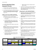
2. Turn the AC Power Switch on the EasyKey and on
the Power Supply Module ON (I = ON, 0 = OFF).
➜ Graco logo, software revision, and “Establishing
Communication” will display, followed by Status
screen. See page 19.
➜ At power up the system defaults to Recipe 61,
which is not a valid recipe number. Initiate a
color change to Recipe 0 or a valid recipe num-
ber (1-60).
➜ In bottom left corner, the system status displays,
which can be Standby, Mix, Purge, or an alarm
notification.
3. Verify that the EasyKey is working. The active recipe
number and Standby mode should be displayed.
4. If this is the first time starting up the system, purge it
as instructed in Purging Fluid Supply System,
page 78. The equipment was tested with lightweight
oil, which should be flushed out to avoid contaminat-
ing your material.
5. Make sure that the EasyKey is in Standby (remove
Mix input).
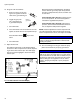
6. Adjust component A, B, and C fluid sup-
plies as needed for your application. Use
lowest pressure possible.
7. Do not exceed the maximum rated work-
ing pressure shown on the system identification
label or the lowest rated component in the system.
8. Open the fluid supply valves to the
system.
9. Adjust the air pressure. Most appli-
cations require about 80 psi (552
kPa, 5.5 bar) air pressure to operate properly. Do
not use less than 75 psi (517 kPa, 5.2 bar).
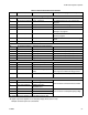
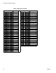
Table 11: Pre-Operation Checklist
✓ Checklist
System grounded
Verify all grounding connections were made. See
the ProMix 3KS Installation manual.
All connections tight and correct
Verify all electrical, fluid, air, and system connec-
tions are tight and installed according to the
Installation manual.
Fluid supply containers filled
Check component A, B, and C and solvent supply
containers.
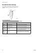
Mix manifold valves set
Check that mix manifold valves are set correctly.
Start with the settings recommended in Mix Mani-
fold Valve Settings, page 68, then adjust as
needed.
Fluid supply valves open and pressure set
Component A, B, and C fluid supply pressures
should be equal unless one component is more
viscous and requires a higher pressure setting.
Solenoid pressure set
75-100 psi inlet air supply (0.5-0.7 MPa, 5.2-7 bar)
F
IG. 70. Power Switches
I = ON
TI12656a TI14372a
FIG. 71. Status Screen
Mix
1
/
4