
User's Manual

Color Change
313885C 83
Color Change
Color Change Procedures
Multiple Color Systems
1. Shut off air to the gun.
2. Place the gun in the gun flush box if used, and close
the lid.
3. Go to Standby mode (remove Mix input).
4. Select the new recipe. Begin the color change
sequence.
5. If a gun flush box is not used, trigger
the gun (manual or automatic) into a
grounded metal pail until the color
change sequence is complete.
NOTE: The color change timer does not start until
the gun is triggered and fluid flow is detected. If no
flow is detected within 2 minutes, the color change
operation aborts. The system enters Standby mode
(remove Mix input) at the previous color.
6. When you are ready to spray, remove the gun from
the gun flush box if used, and close its door (manual
and semi-automatic systems only).
NOTE: The gun flush box door must be closed for
the atomizing air valve to open.
7. Enter Mix mode to start spraying.
Single Color Systems
1. Follow procedure for Purging Fluid Supply Sys-
tem, page 78.
2. Load the new color. See Start Up, page 69.
3. Enter Mix mode to start spraying.
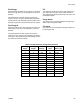
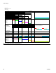
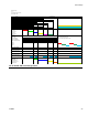
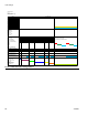
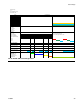
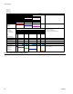
Color Change Sequences
FIG. 79 through FIG. 88 illustrate various color change
sequences. See Table 12 to determine which figure to
reference, based on the recipe change and system con-
figuration. The time sequences are detailed in the fol-
lowing paragraphs.
NOTE: See Setup Mode on page 25 to select purge
sources and set desired purge, chop, and fill times.
NOTES:
• The system uses old recipe data for the purge cycle.
However, it opens the new color/catalyst valve
based on the new recipe data.
• The system uses the new recipe data for the fill
cycle.
• For the one gun flush box (GFB) option, the spray
gun must be inserted in the GFB during the entire
color change cycle (purge and fill). The GFB trigger
output will be on during the recipe change cycle.
• For the two gun flush box (GFB) option, both spray
guns must be inserted in the GFBs during the entire
color change cycle (purge and fill). The system will
turn each GFB trigger output on and off based on
the preset time for each gun.
• For Special Outputs options, the system will turn
each output on and off based on the preset times.
Each Special Output has two different start times
and durations.
• For systems without dump valves, the First Purge
begins after the Color/Catalyst/Component C
Change steps are completed.
• Dump Valve B is required for a Catalyst Change
system.
• Dump Valve C is required for a Component C
Change system.
• When going from Recipe X to Recipe 0, only the
purge cycle data from Recipe 0 is used.
• When going from Recipe 0 to Recipe X, only the fill
cycle data from Recipe X is used.