Operation HTX 2030 313888E EN -For Portable Airless and Air-Assisted Spraying of Water-Based Architectural Coatings with Base Coat Pump-For Airless Spraying Architectural Coatings and Paints with Top Coat Pump- IMPORTANT SAFETY INSTRUCTIONS Read all warnings and instructions in this manual. Save these instructions. Model Number: 257369 (HTX2030 FreeFlo Inline Gun) Model Number: 278675 (HTX2030 AirSpray Trigger Gun) Maximum Working Pressure: Base Coat Pump: 1000 psi (69 bar, 6.
Contents Contents Contents . . . . . . . . . . . . . . . . . . . . . . . . . . . . . . . . . . 2 Warnings . . . . . . . . . . . . . . . . . . . . . . . . . . . . . . . . . 3 Product Overview . . . . . . . . . . . . . . . . . . . . . . . . . . 5 HTX 2030 with Base Coat Pump (257369) . . . . . 5 Top Coat Pump (Kit 24B140) . . . . . . . . . . . . . . . 6 Component Identification - Sprayer . . . . . . . . . . .
Warnings Warnings The following warnings are for the setup, use, grounding, maintenance, and repair of this equipment. The exclamation point symbol alerts you to a general warning and the hazard symbols refer to procedure-specific risks. When these symbols appear in the body of this manual or on warning labels, refer back to these Warnings. Product-specific hazard symbols and warnings not covered in this section may appear throughout the body of this manual where applicable.
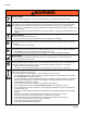
Warnings WARNING RECOIL HAZARD Gun may recoil when triggered. If you are not standing securely, you could fall and be seriously injured. PRESSURIZED ALUMINUM PARTS HAZARD Use of fluids that are incompatible with aluminum in pressurized equipment can cause serious chemical reaction and equipment rupture. Failure to follow this warning can result in death, serious injury, or property damage.
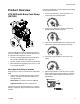
Product Overview Product Overview Flow rate is dependent on engine speed and the setting of the pump control knob. HTX 2030 with Base Coat Pump (257369) 1. Flow 3 (fully clockwise) - allows the pump to run continuously with minimal pulsation: ti13756a 2. Flow 2 (near middle of the rotation) reduces flow slightly by briefly interrupting pump: ti13757a 3.
Product Overview Top Coat Pump (Kit 24B140) When Top Coat Pump is Installed • Pump will only run when on/off switch is in ON position and pump control is rotated clockwise away from OFF position • Pump control setting adjusts sprayer pressure a. Rotating knob fully clockwise allows sprayer to reach maximum working pressure of 3300 psi (228 bar, 22.8 MPa) ti13653a The pump on the HTX 2030 Sprayer can also be switched out with a Top Coat Kit 24B140 (purchased separately).
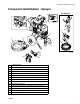
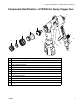
Component Identification - Sprayer Component Identification - Sprayer Top Coat Kit 14 1 2 3 9 10 8 5 4 12 11 7 ti14415b 13 6 1 ON/OFF Switch 2 Prime Switch (used with Base Coat Pump) 3 Pump Control Knob 4 Heavy Texture Material Hose (used with Base Coat Pump) 5 Applicator Switch (used with Base Coat Pump--on Hose) 6 Applicator (Base Coat) (Model 257369) 7 Pump (Base Coat) 8 Over Pressure Relief Valve 9 Pump (Top Coat) 10 Spray Gun (Top Coat) 11 Paint/Texture Material Hose (use
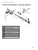
Component Identification - Base Coat Applicator Component Identification - Base Coat Applicator 8 1 7 9 10 2 11 3 6 4 5 ti14357a 8 1 Applicator 2 Air Hose Adapter and Air Adjustment Valve 3 Airless Filter or Air Passage Plug 4 Filter Support 5 Airless Spray Assembly 6 Airless Spray Tip Nozzle 7 Air Nozzle (4 mm, 6mm, 8mm, 10mm) 8 Air Nozzle Cleaner 9 Cleaning Brush 10 Cleaning Ball 11 Retaining Nut 313888E
Component Identification - HTX2030 Air Spray Trigger Gun Component Identification - HTX2030 Air Spray Trigger Gun 11 1 2 3 7 4 5 6 10 9 8 12 ti21036a 1 HTX2030 Air Spray Trigger Gun 2 Nozzle, Size #1, Size #2, Size #3 3 Adapter, Housing 4 Ring, Retaining Nozzles 5 Tip, Disc, Spray, 1/8 in. (3 mm), 1/4 in. (6.3 mm), 5/16 in. (8 mm), 3/8 in. (9.
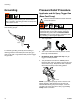
Grounding Grounding Pressure Relief Procedure Applicator and Air Spray Trigger Gun (Base Coat Pump) The equipment must be grounded to reduce the risk of static sparking. Static sparking can cause fumes to ignite or explode. Grounding provides an escape wire for the electric current. Ground sprayer with grounding clamp to earth ground when flushing sprayer. Follow the Pressure Relief Procedure whenever you see this symbol. This equipment stays pressurized until pressure is manually relieved.
Pressure Relief Procedure Spray Gun (Top Coat Pump) 4. Lock gun trigger safety. Open pressure prime/drain valve. Leave valve open until ready to spray again. ti13131a 1. Lock gun trigger safety and turn engine OFF. ti14632a ti13131a 2. Turn on/off switch to OFF and turn pressure control knob fully counterclockwise.
Start Engine Start Engine 5. Pull starter rope. 1. Move fuel valve to OPEN. ti5263a 6. After engine starts, move choke to OPEN. ti5248a 2. Move choke to CLOSED. ti5264a 7. Set throttle to desired setting. ti5249a 3. Set throttle to FAST. ti5251a ti5250a 4. Set engine switch to ON.
Setup Setup Prime Pump NOTICE DO NOT USE MATERIALS THAT CURE RAPIDLY! Materials with a fast curing time could plug the pump, hose, gun, or applicator. 1. Start gasoline engine and adjust speed to half throttle. Turn prime/drain valve to DRAIN. 1. Fill mixing pail with pre-mixed texture material. Mix per material manufacturer instructions. ti14632a 2. Place material hose outlet over supply pail. ti4118a Add approximately 10% water to texture mix or per material manufacturer instructions.
Setup 5. Turn on/off switch OFF and turn drain valve knob to SPRAY. Spray With Airless Tip 1. Install filter and tip extension. ti10796b ti13648a 6. Turn on/off switch ON, and run pump until a steady stream of material flows from material hose. Turn on/off switch to OFF and turn drain valve knob to DRAIN. ti13649a 7. Connect applicator to material hose. 2. Insert metal seat and OneSeal. Insert Switch Tip. Screw assembly onto applicator. ti13650a 3.
Setup Spray Without Air - Clear Clog 1. Relieve Pressure, page 10. 4. Turn air valve OFF. Connect applicator to material hose and air hose. Air supply minimum requirements vary with material thickness and desired thickness. 2. Rotate SwitchTip to Clear position. Aim applicator at floor and turn pump ON. When clog clears, turn pump OFF. ti11714a 3. Rotate SwitchTip to Spray position. Turn pump ON. Spray test pattern.
Setup 8. Spray test pattern. Aim applicator at floor. Turn air valve ON. Move applicator to spray surface. 3. Turn air valve OFF. Connect applicator to material hose and air hose. Air supply minimum requirements vary with material thickness and desired thickness. ti13646a 9. Adjust air valve and/or select alternative nozzle size (4 - 10mm) for desired finish.
Setup 7. Turn air valve on and adjust air valve and/or select alternative nozzles or spray discs to achieve desired pattern. 2. Screw assembly onto gun. Hand tighten. 1/8 in. 1/4 in. ti5801a 3/8 in. ti21034a 3. Trigger gun and spray test pattern. Slowly adjust pressure to eliminate heavy edges. Use smaller tip size if pressure adjustment can not eliminate heavy edges. 5/16 in. 8. Spray test pattern. Move applicator to spray surface.
Cleanup Cleanup 5. Base Coat Pump: Disconnect material hose from pump outlet. 1. Turn on/off switch OFF. ti13639a 6. Insert wet cleaning ball into hose (Base Coat Only). Connect material hose to pump outlet. ti10796b 2. Perform Pressure Relief procedure, page 10. 3. Place pump in pail of clean water. ti13643a ti13638a 7. Hold material hose over waste pail. ti13644a 4. Shut OFF air if spraying with air. Remove applicator from material and air hoses. ti13640a 8.
Cleanup 9. Run pump until cleaning ball exits material hose. Save cleaning ball (Base Coat Only). 14. Add additional water and repeat steps 12 - 13 if necessary. ti4551c ti13839a 10. Turn on/off switch OFF and turn prime/drain valve to DRAIN. Clean outside of pump and suction tube with brush and water. ti10796b 15. Open prime/drain valve and turn prime switch ON to flush valve. ti14632a 11. Connect applicator to material hose. Close prime/drain valve. ti14632a 16.
Cleanup 18. Remove and thoroughly clean applicator, spray tip nozzle and guard with brush. 19. Turn on/off switch OFF when valve is thoroughly flushed. 20. Clean hardened material from applicator nozzles with air nozzle cleaner. NOTICE Do not use air nozzle cleaner to clean applicator check valve or airless spray tip nozzle. Damage will occur. Remove air check valve from applicator to clean hardened material from interior of applicator.
Digital Tracking System (DTS) Digital Tracking System (DTS) Main Menu 4. Short press DTS button to move to Engine RPM. Close cover when spraying to protect display. ti13761a ti5802a 1. Perform Startup steps 1 - 2. 5. Short press DTS button to return to Pressure. • Open drain valve • Turn pump control counterclockwise to lowest setting • Set applicator switch to OFF 2. Start Engine, page 12.
Digital Tracking System (DTS) Secondary Menu - Stored Data Mode 6. Short press DTS button and Base Coat hours displays. • Open drain valve Short press DTS button and Top Coat hours display. • Turn pump control counterclockwise to lowest setting Short press DTS button and Engine hours display. • Set applicator switch to OFF 1. Start Engine, page 12. Pressure display appears. ti13787a ti5812a 2. Press and hold DTS button and turn applicator switch ON. 7.
Digital Display Messages Digital Display Messages DISPLAY* No Display SPRAYER OPERATION INDICATION ACTION Sprayer may be pressurized Loss of power or display not connected Check power source. Relieve pressure before repair or disassembly. Verify display is connected. Sprayer may be pressurized Pressure less than 60 psi (4 bar, 0.
Maintenance Maintenance AFTER EACH 100 HOURS OF OPERATION • Change engine oil. Reference Honda Engines Owner’s Manual for correct oil viscosity. NOTICE For detailed engine maintenance and specifications, refer to separate Honda Engines Owner’s Manual (supplied). DAILY SPARK PLUG Use only BPR6ES (NGK) or W20EPR-U (NIPPONDENSO) plug. Gap plug to 0.028 to 0.031 in. (0.7 to 0.8 mm). Use spark plug wrench when installing and removing plug.
Technical Data Technical Data Honda GX 200 Engine: ANSI Power Rating @ 3600 rpm 6.5 Horsepower (4.8 kW) Maximum Working Pressure: Base Coat Pump Top Coat Pump 1000 psi (69 bar, 6.9 MPa) 3300 psi (228 bar, 22.8 MPa) Noise Level: Sound Power Sound Pressure 105 dBa per ISO 3744 96 dBa measured at 3.1 ft (1 m) Maximum Delivery Rating: Base Coat Pump Top Coat Pump 3.0 gpm (11.36 liter/min) 2.20 gpm (8.33 liter/min) Maximum Tip Size: Base Coat Pump Top Coat Pump 1 applicator with .071 in.
Notes Notes 26 313888E
Notes Notes 313888E 27
Graco Standard Warranty Graco warrants all equipment referenced in this document which is manufactured by Graco and bearing its name to be free from defects in material and workmanship on the date of sale to the original purchaser for use. With the exception of any special, extended, or limited warranty published by Graco, Graco will, for a period of twelve months from the date of sale, repair or replace any part of the equipment determined by Graco to be defective.