Instructions-Parts Reactor® E-10hp 332144C EN For spraying or dispensing polyurea coatings and polyurethane foam. For professional use only. Not approved for use in explosive atmospheres or hazardous locations. 3000 psi (21 MPa, 207 bar) Maximum Working Pressure Important Safety Instructions Read all warnings and instructions in this manual. Save these instructions.
Contents Warnings . . . . . . . . . . . . . . . . . . . . . . . . . . . . . . . . . 3 Important Isocyanate (ISO) Information . . . . . . . . 6 Isocyanate Conditions . . . . . . . . . . . . . . . . . . . . 6 Material Self-ignition . . . . . . . . . . . . . . . . . . . . . . 6 Keep Components ISO and RES Separate . . . . 6 Moisture Sensitivity of Isocyanates . . . . . . . . . . . 6 Foam Resins with 245 fa Blowing Agents . . . . . . 6 Changing Materials . . . . . . . . . . . . . . . . . . . . . . . 7 Systems .
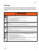
Warnings Warnings The following warnings are for the setup, use, grounding, maintenance, and repair of this equipment. The exclamation point symbol alerts you to a general warning and the hazard symbols refer to procedure-specific risks. When these symbols appear in the body of this manual or on warning labels, refer back to these Warnings. Product-specific hazard symbols and warnings not covered in this section may appear throughout the body of this manual where applicable.
Warnings WARNING FIRE AND EXPLOSION HAZARD Flammable fumes, such as solvent and paint fumes, in work area can ignite or explode. To help prevent fire and explosion: • Use equipment only in well ventilated area. • Eliminate all ignition sources; such as pilot lights, cigarettes, portable electric lamps, and plastic drop cloths (potential static arc). • Keep work area free of debris, including solvent, rags and gasoline.
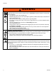
Warnings WARNING EQUIPMENT MISUSE HAZARD Misuse can cause death or serious injury. • Do not operate the unit when fatigued or under the influence of drugs or alcohol. • Do not exceed the maximum working pressure or temperature rating of the lowest rated system component. See Technical Data in all equipment manuals. • Use fluids and solvents that are compatible with equipment wetted parts. See Technical Data in all equipment manuals. Read fluid and solvent manufacturer’s warnings.
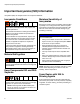
Important Isocyanate (ISO) Information Important Isocyanate (ISO) Information Isocyanates (ISO) are catalysts used in two component materials. Isocyanate Conditions Spraying or dispensing materials containing isocyanates creates potentially harmful mists, vapors, and atomized particulates. Read material manufacturer’s warnings and material MSDS to know specific hazards and precautions related to isocyanates.
Important Isocyanate (ISO) Information Changing Materials NOTICE Changing the material types used in your equipment requires special attention to avoid equipment damage and downtime. • When changing materials, flush the equipment multiple times to ensure it is thoroughly clean. • Always clean the fluid inlet strainers after flushing. • Check with your material manufacturer for chemical compatibility.
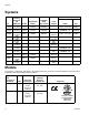
Systems Systems Part APT100 P2T100 APT900 APT901 APT902 P2T900 P2T901 P2T902 24T900 24T901 24T902 Maximum Working Pressure, psi (MPa, bar) 3000 (21, 207) 3000 (21, 207) 3000 (21, 207) 3000 (21, 207) 3000 (21, 207) 3000 (21, 207) 3000 (21, 207) 3000 (21, 207) 3000 (21, 207) 3000 (21, 207) 3000 (21, 207) Gun Volts Proportioner Model Unheated Hose 35 ft (10.
Related Manuals Related Manuals The following manuals are for Reactor E-10hp components and accessories. Some are supplied with your package, depending on its configuration. Manuals are also available at www.graco.com. Displacement Pump Part No. Description 311076 Instruction-Parts Manual (English) Fusion Air Purge Spray Gun Part No. Description 309550 Instruction-Parts Manual (English) Probler P2 Spray Gun Part No. Description 313213 Instruction-Parts Manual (English) Probler P2 Recirculation Kit Part No.
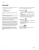
Overview Overview The Reactor E-10hp is a portable, electric-powered, 1:1 mix ratio proportioner for use with: The Reactor E-10hp has two recirculation speeds, slow and fast, and an adjustable pressure output. • • • Slow Recirculation Polyurea Polyurea hybrid coatings Polyurethane foam Material may be applied with impingement mix spray guns. The Reactor E-10hp is gravity-fed from 6 gal. (22.7 liter) supply tanks mounted on the unit.
Component Identification Component Identification Key for FIG.
Controls and Indicators Controls and Indicators See Controls and Indicators identification table, page 13. NOTICE To prevent damage to soft key buttons, do not press the buttons with sharp objects such as pens, plastic cards, or fingernails. Heater Controls AL AM AA AE AB AN AF AC AD AR AP AO AS AG °F AH °C AJ AK FIG. 2. Heater Controls and Indicators System Controls AW AY AX - STATUS 1 I AT 0 I 2 3 4 5 6 ++ 7 AV 8 -- 9 10 AU FIG. 3.
Controls and Indicators Controls and Indicators Key Name Heater Controls AA ISO Setpoint Increase AB ISO Setpoint Decrease AC RES Setpoint Increase AD RES Setpoint Decrease AE ISO Heater On/Off Key AF RES Heater On/Off Key AG Actual Temperature Key AH Target Temperature Key AJ AK AL Temperature Scale Key °F Temperature Scale Key °C Temperature Display Heater Indicators AM ISO Heater Activity AN RES Heater Activity Description Increases the temperature setpoint by one degree in the unit
Controls and Indicators Motor/Pump Control Function Knob Heater Control Diagnostic Codes Use knob (AV) to select desired function. Heater control diagnostic codes appear on the temperature display. These alarms turn off heat. Icon Setting Function Stop/Park Stops motor and automatically parks pumps. Slow Recirc Slow recirculation speed. Fast Recirc Fast recirculation speed.
Setup Setup Locate Reactor 1. Locate Reactor on a level surface. To avoid electric shock, always unplug both cords before servicing Reactor and wait one minute. 2. Do not expose Reactor to rain. Electrical Requirements Heater Power 1 Improper wiring may cause electric shock or other serious injury if work is not performed properly. All electrical wiring must be done by a qualified electrician and comply with all local codes and regulations. 2 TI7061a 1.
Setup Ground System 2. Connect recirculation hoses from gun recirculation ports to connections (S). The equipment must be grounded to reduce the risk of static sparking and electric shock. Electric or static sparking can cause fumes to ignite or explode. Improper grounding can cause electric shock. Grounding provides an escape wire for the electric current. S R (RES) Reactor: grounded through power cord. R S (ISO) Generator (if used): follow your local code.
Setup Fill Wet-Cups 1. Lift hose rack. Remove tank cover and pour ISO into tank (red side, with desiccant filter in cover). Keep the felt washers in the pump wet-cups saturated with Graco ISO pump oil, Part No. 217374. The lubricant creates a barrier between the ISO and the atmosphere. Pump rod and connecting rod move during operation. Moving parts can cause serious injury such as pinching or amputation. Keep hands and fingers away from wet-cup during operation.
Setup Purge Air and Flush Fluid From Lines To avoid fire and explosion: 5. Turn on Motor Power. System status indicator (AY) should turn on. 6. Set Recirc/Spray valves to Recirc. • Flush equipment only in a well-ventilated area. • Ensure main power is off and heater is cool before flushing. • Do not turn on heater until fluid lines are clear of solvent. 1. Remove both recirculation tubes (P) from the tanks and secure each one in a dedicated waste container. ti21495a 7.
Startup Startup d. Press Heated fluid can cause equipment surfaces to become very hot. To avoid severe burns: to display actual temperatures. 5. Circulate through heater until temperature readouts display desired temperature. See Table 6. • Do not operate Reactor without all covers and shrouds in place. • Do not touch hot fluid or equipment. • Allow equipment to cool completely before touching it. 6. Adjust heat controls as necessary for a stable spray temperature.
Startup Heatup Guidelines Heat Management Tips The fluids must be circulated from the pumps through the heater, hoses, and back to the tanks to ensure warm fluids are supplied to the gun. • Heaters perform better with lower flow rates or smaller mix modules. • Triggering the gun for short periods helps maintain efficient heat transfer, keeping material at the desired temperature. Triggering the gun for a long period may not allow enough heating time, depending on material temperature in tanks.
Spraying Spraying NOTE: Air is supplied to spray gun with gun piston safety lock or trigger safety lock engaged and gun fluid manifold valves closed (if present). 4. Check fluid pressure gauges to ensure proper pressure balance. If imbalanced, reduce pressure of higher component by slightly turning Recirc/Spray valve for that component toward Recirc, until gauges show balanced pressures.
Pause Pause Refill Tanks To bring the hose and gun back to spray temperature after a brief break, use the following procedure. Material can be added to the tanks at any time. See Fill Fluid Tanks, page 17. 1. Engage piston safety lock or trigger safety lock. NOTE: If you are operating at high temperatures or flow rates, follow Pause instructions to bring tanks up to temperature. NOTICE Fusion Probler 2.
Pressure Relief Procedure Pressure Relief Procedure Shutdown Follow the Pressure Relief Procedure whenever you see this symbol. NOTE: For longer breaks (more than 10 minutes) use the following procedure. If you will be shutdown for more than 3 days, first see Flushing, page 25. 1. Shut off Heater Power. This equipment stays pressurized until pressure is manually relieved.
Maintenance Maintenance • Check pump wet-cups fluid level daily, page 17. • Throat u-cup is not adjustable. Do not overtighten packing nut/wet-cup. • Keep component ISO from exposure to moisture in atmosphere, to prevent crystallization. • Wipe supply tank lid o-ring, inner rim, and inner tank walls daily to prevent ISO crystallization. Keep film of grease on o-ring and inside of lid. • Check desiccant filter weekly. Filter is blue when fresh, and turns pink when saturated.
Flushing Flushing 3. Shut off Heater Power. Allow system to cool. To avoid fire and explosion: • Flush equipment only in a well-ventilated area. • Ensure main power is off and heater is cool before flushing. • Do not turn on heater until fluid lines are clear of solvent. 4. Remove recirculation tubes (P) from supply tanks and place in original containers or waste containers. P • Generally, flush if you will be shut down for more than 3 days.
Flushing 9. Set function knob to Fast Recirc . Pump solvent through system to waste containers. 2 1 3 5 6 + 7 8 - . 13. Solvent flushing is a two step process. Go back to step 4, drain solvent, and flush again with fresh solvent. 4 0 12. Set function knob to Stop/Park 9 10 ti31496a 10. When nearly clear solvent comes from recirculation tubes, set function knob to Stop/Park recirculation tubes toSTATUS supply tanks. 2 1 3 . Return 4 0 5 6 + 14.
Troubleshooting Troubleshooting Pump Control Status Codes Determine the status code by counting the number of times the system status indicator blinks. The status indicator will blink 1-19 times to indicate a status code. Multiple active status codes are separated by a longer duration pause. To turn off automatic shutdown and/or change pressure tolerances for status code 2, see DIP Switch Settings, page 29. Deviation can occur if power is turned on if function knob (AV) is not set to Park/Off.
Troubleshooting Status Code 6: High Motor Temperature Motor is running too hot. 1. Reduce pressure duty cycle, gun tip size, or move Reactor to a cooler location. Allow 1 hour for cooling. 2. Check fan operation. Clean fan and motor housing. 3. Check J9 overtemperature connector on control board. 3. Check J6 connections on control board. See Table 8, page 45.
Troubleshooting DIP Switch Settings To avoid electric shock, always unplug both power cords before servicing Reactor and wait one minute. 1. Turn power off and unplug power cords from wall outlets. 2. Remove screws and display cover (26). 26 ti21923a 3. Locate the DIP switch on the control board. FIG. 6: DIP Switch 4. Set DIP switches to the desired positions. See DIP Switch Settings and Functions, page 30 5. Replace display cover (26) and plug in unit. 6.
Troubleshooting DIP Switch Settings and Functions DIP Switch Settings and Functions DIP Switch and Function OFF ON DIP Switch 1 DEVIATION DEVIATION AND SHUTDOWN If selected, displays a status code or displays a status code and causes shutdown if the pressure imbalance exceeds selection made in DIP Switch 2. DIP Switch 2 Select pressure imbalance limits, that if exceeded, will cause See Dip Switch 1 and 2 Settings table, page a deviation and a shutdown (if enabled).
Troubleshooting Heat Control Diagnostic Codes • Failed heater element where thermocouple is installed. Heat control diagnostic codes appear on the temperature display. • Loose wire These alarms turn off heat. Codes E03 and E04 can be cleared by pressing E01 Checks . Troubleshooting this equipment requires access to parts that may cause electric shock or other serious injury if work is not performed properly. Have a qualified electrician perform all electrical troubleshooting.
Troubleshooting 4. Remove connector B from heater control module and check continuity of thermocouples by measuring resistance across pins on the plug end. 5. Verify fluid temperature, using an external temperature sensing device.
Troubleshooting Reactor Electronics 2. Shut off Motor Power. 3. Relieve pressure, page 23. Before performing any troubleshooting procedures: 4. Allow equipment to cool. 1. Shut off Heater Power. 5. Try the recommended solutions in the order given for each problem, to avoid unnecessary repairs. Also, determine that all circuit breakers, switches, and controls are properly set and wiring is correct before assuming there is a problem. PROBLEM Temperature display does not illuminate.
Troubleshooting PROBLEM CAUSE Display does not respond properly to Poor display connection. button pushes. Display cable damaged or corroded. SOLUTION Check cable connections, FIG. 23 on page 72. Replace damaged cable. Clean connections, FIG. 23 on page 72. Replace damaged cable. Ribbon cable on display circuit board Connect cable, FIG. 23 on page 72, disconnected or broken. or replace. Fan not working. 34 Broken display button. Replace, page 42. Loose wire. Check fan wire. Defective fan.
Troubleshooting Heaters 2. Shut off Motor Power. Before performing any troubleshooting procedures: 3. Relieve pressure, page 23. 1. Shut off Heater Power. 4. Allow equipment to cool. Try the recommended solutions in the order given for each problem, to avoid unnecessary repairs. Also, determine that all circuit breakers, switches, and controls are properly set and wiring is correct before assuming there is a problem. PROBLEM Primary heater(s) does not heat. CAUSE SOLUTION Heat turned off.
Troubleshooting Proportioner 2. Shut off Motor Power. Before performing any troubleshooting procedures: 3. Relieve pressure, page 23. 1. Shut off Heater Power. 4. Allow equipment to cool. Try the recommended solutions in the order given for each problem, to avoid unnecessary repairs. Also, determine that all circuit breakers, switches, and controls are properly set and wiring is correct before assuming there is a problem. PROBLEM Reactor does not operate. CAUSE No power.
Troubleshooting PROBLEM One side doesn’t come up to pressure in spray mode. CAUSE Low fluid in tank. SOLUTION Refill. Dirty or damaged Recirc/Spray valve. Clean or repair, page 40. Plugged fluid inlet strainer. Clear, see page 24. Pump intake valve plugged or stuck open. Clean pump intake valve. See page 41. Material is too viscous to pump. Warm material before adding to tanks. Pressure is higher on one side when Pump intake valve partially plugged. setting pressure with function knob.
Troubleshooting PROBLEM ISO side rich; lack of RES side. RES side rich; lack of ISO side. CAUSE ISO side gauge is low. RES side restriction downstream of gauge. Check gun check valve screen, mix module, or mix manifold restrictor. RES side gauge is low. RES side material supply problem. Check RES side inlet strainer and pump intake valve. ISO side gauge is low. ISO side material supply problem. Check ISO side inlet strainer and pump intake valve. RES side gauge is low.
Repair Repair Before Beginning Repair Repairing this equipment requires access to parts which may cause electric shock or other serious injury if work is not performed properly. Have a qualified electrician connect power and ground to main power switch terminals, see page 15. Be sure to shut off all power to the equipment before repairing. Remove Supply Tank 1. See Before Beginning Repair, page 39. 2. Relieve pressure, page 23. 3. Flush, page 25. 4. Place waste container under y-strainer. 1.
Repair Replace Recirc/Spray Valves 8. Disconnect swivel elbow at pump fluid inlet. 9. Remove six screws (28) holding tank (27) to cart frame. S 27 1. See Before Beginning Repair, page 39. 2. Relieve pressure, page 23. 3. See FIG. 7. Disassemble Recirc/Spray valves. Clean and inspect all parts for damage. 4. Ensure that the seat (453a) and gasket (453b) are positioned inside each valve cartridge (453). 28 ti21837a 10. Loosen nut and slide tank level sensor (S) away from the tank. 5.
Repair Displacement Pump NOTE: Use dropcloth or rags to protect Reactor and surrounding area from spills. 8. Remove pump rod cover (222). Push clip up in back and push pin (217) out. Loosen locknut (218) by hitting firmly right-to-left with a non-sparking hammer. Unscrew pump. See manual 311076 for pump repair and parts. 9. Install pump in reverse order of disassembly, following all notes in FIG. 8. Clean strainer (51). Reconnect fluid inlet (C) and outlet (D) lines. 1.
Repair Control Panel Replace Function Knob/Potentiometer Replace Temperature Display 1. See Before Beginning Repair, page 39. 2. Remove screws (21) and back cover (26). NOTICE Before handling board, put on a static conductive wrist strap to protect against static discharge which can damage board. Follow instructions provided with wrist strap. 3. Disconnect potentiometer wires from J5 on motor control board (354). See FIG. 12, page 45. 4. See FIG. 9.
Repair 353 373 360 352 351 363 354 ti21841a 357 FIG.
Repair Motor Control Replace Control Board Power Bootup Check NOTE: Power must be on to check. See FIG. 11 or location. Function is: • • • Motor ready: LED on. Motor not ready: LED off. Status code (motor not running): LED blinks status code. Multiple status codes are separated by a longer LED off duration. • NOTE: Check motor before replacing board. See Test Motor, page 53. 1. See Before Beginning Repair, page 39. 2. Remove access cover (26) on back of cart to expose control board (354).
Repair Table 8: Control Board Connectors (see FIG.
Repair Replace Temperature Control Modules 4. Disconnect all cables and connectors from temperature control module (59). NOTICE Before handling assembly put on a static conductive wrist strap to protect against discharge which can damage assembly. Follow instructions provided with wrist strap. 59 56 1. See Before Beginning Repair, page 39. 2. Remove heater shroud (89) and electronics cover (55). ti21844a FIG. 13 55 89 5. Remove hex nut (56) and replace defective module. 6.
Repair Temperature Control Modules Connections Table 9: Heater Control Module Connections Description Table 9: Heater Control Module Connections Connector Description Connector 120V DATA (A) Sensor (B) DISPLAY (C) COMMUNICATION (D) PROGRAM (E) BOOT (F) POWER/RELAY (G) 230V Not used See Table 11 Display Communication to power boards Software programming Software bootloader 120V 230V Circuit board power input and contactor control output Table 10: Temperature Power Module Connections Connector CO
Repair Heater 4. Disconnect heater element wires from heater wire connector. Test with ohmmeter. Replace heater element if the resistance reading does not fall within the range. Test Heater Element 1. See Before Beginning Repair, page 39. Heater Voltage Heater Wattage Per Zone Element Wattage Ohms 120 1500 500 24-32 1000 12-16 620 73-94 1380 32-43 2. Wait for heater to cool. 3. Remove heater shroud (90) and electronics cover (55). 230 2000 Remove Heater Element 1.
Repair Thermocouple 8. Replace thermocouple, FIG. 16. 1. See Before Beginning Repair, page 39. a. Remove protective tape from thermocouple tip (T). b. Apply PTFE tape and thread sealant to male threads and tighten thermocouple housing (H) into adapter (305). 2. Wait for heaters to cool. 3. Remove heater shroud (90) and electronics cover (55). See FIG. 15, page 48. 4. Loosen and remove temperature control module bracket mounting fasteners (56).
Repair Overtemperature Switch a. Remove supply tank, page 39. 1. See Before Beginning Repair, page 39. b. Follow transducer cable on cart frame and cut zip ties. Disconnect transducer from pump outlet manifold. c. 2. Wait for heaters to cool. 3. Remove heater shroud (90) and electronics cover (55). See FIG. 15, page 48. 4. Disconnect one leadwire from overtemperature switch (308), FIG. 16. Test across switch with ohmmeter. Resistance must be approximately 0 ohms. 5.
Repair Drive Housing 4. Install gear reducer (214) and crankshaft (210) into motor end bell (MB). NOTE: Crankshaft (210) must be in line with crankshaft at other end of motor. Pumps will move up and down together. Removal 1. See Before Beginning Repair, page 39. 2. Remove screws (207) and end covers (229), see FIG. 18. NOTE: Examine connecting rod (216). If rod needs replacing, first remove the pump (219), page 41.
Repair Replace Cycle Counter Switch 223 NOTE: RES side drive housing cover (229) includes the cycle counter switch (223), mounted in the cover. When reassembling, be sure to install cover with switch on RES side. 0.6 in. (15.2 mm) from inside edge 1.0 in. (25.
Repair Electric Motor Test Motor If motor is not locked up by pumps, it can be tested using a 9 V battery. NOTICE To prevent dropping the motor, two people may be required to lift. 10. Remove screws (15) holding motor (201) to bracket. Lift motor off unit. 1. Open recirculating valves. 2. Disconnect motor connections from control board, see FIG. 12, page 45. Touch jumpers from battery to motor connections. Motor should turn slowly and smoothly. Removal 11.
Repair Motor Brushes 9. See instruction sheet 406582, included with Brush Repair Kit 287735. NOTE: Replace brushes worn to less than 1/2 in. (13 mm). Brushes wear differently on each side of motor; check both sides. Brush Repair Kit 287735 is available; kit includes instruction sheet 406582. NOTE: Motor commutator should be smooth. If not, resurface commutator or replace motor. ti21916a 1. See Before Beginning Repair, page 39. FIG. 19: Motor Brushes 2. Relieve pressure, page 23. 3.
Repair Tank Fluid Level Sensors 6. Route new tank level sensor cable through grommet on bottom of cart and through the grommet on bottom of control panel. Connect new level sensor (57) to J6. Adjust Adjust position of tank fluid level sensor (57) so that the sensor contacts the surface of the tank. 1. Loosen sensor jam nuts and press sensor (57) against the tank. 2. Spin on inner jam nut until flush, then tighten inner jam nut one more turn. 3. Retighten outer jam nut. 7.
Repair Reset Sensitivity The tank fluid level sensor sensitivity may need to be adjusted when: • A new tank has a different insulation density than the previous tank. • Material build-up is on the inside or outside of the tank. Adjust sensitivity rather than thoroughly cleaning the tank. 7. Slowly turn the adjustment screw (S) counterclockwise an additional 1/2 turn. NOTE: The yellow LED should stay turned off. 8. Fill tank with desired material and verify that sensor detects material.
Parts Parts System Packages 104 101 16W239 15G958 15G962 102 103 Proportioner Hose Gun 101 see page 58 102 see page 71 103 APT100 24T100 25R000 P2T100 24T100 APT900 System Package * Power Cord Adapter 104 Part No.
Parts E-10hp Proportioners 24T100, 120 V, Proportioner 24R900, 230 V, Proportioner 26 92 102 21 94 98 93 25 24 2 91 49 97 42 99 50 96 97 84 90 31 77 5 42 32 28 96 89 97 49 48 33 56 29 35 99 55 30, 30a 27 56 ti21853b 58 332144C
Parts 1 8 6 4 3 5 99 6 7 2 41 40 39 3 9 10 38 37 11 12 21 56 11 36 13 56 66 71 73 72 66 67 58 10 70 59 8 4 64 64 66 56 59 10 56 60 68 66 21 69 65 58 74 56 332144C 61 56 ti21855b 59
Parts 47 22 19 47 18 46 17 9 16 45 44 42 43 11 21 57 7 20 21 45 46 14 42 43 44 52 57 54 15 52 11 6 ti21854a 53 60 332144C
Parts 1 Apply sealant to all non-swiveling pipe threads. 8 Orient SSR with terminals 1 and 2 towards the top. 2 Apply sealant to threads of nut cap. 9 Orient fan to flow down and connector plug towards the back. 3 Apply lubricant to thread and axle of cart. 10 Orient heater module with fins outwards. 4 Apply even distribution of thermal grease on bottom of metal surface of solid state relays. 11 Assemble sensor flush to tank surface. 12 5 Torque to 125 in.-lbs (14 N•m).
Parts Ref. 27 28 29 30 30a 31 32 33 35 36 37 38 Part 24T973 111800 127148 24T975 24T975 24K976 101044 119973 24K984 162453 100176 24K977 38a 39 40 41 42 43 44 45 46 47 48 49 50 114228 157350 104641 169970 116704 117506 --556765 24T977 24T978 24T979 24T980 24T981 62 Description TANK SCREW, cap, hex hd SCREW, set, 7/16-14, 1/2, black LID; includes o-ring (30a) O-RING MUFFLER,1/4 NPT WASHER, plain CABLE, sst lanyard; 14 in.
Parts Ref.
Parts Ref. 71 72 73 74† 75† 76 77 78✖† 79✖† 80✖† 81✖† 82✖† 83 84 85 88✖† 89 90 91 92 93 94 95 96 97 98▲ 99▲ 104 Part Description 24T993 RELAY, 12V 255043 HOLDER, fuse terminal block; 5 x 20mm 255023 FUSE, 5A, 5 x 20 mm 127239 CONNECTOR, 5 pin 127240 CONNECTOR, 10 pin 120748 CONNECTOR, 2 pin 127237 CONNECTOR, 6 pin 116171 BUSHING, strain relief 16W761 BUSHING, strain relief 24T994 HARNESS, POWER; see FIG. 23 on page 72. 24T995 CABLE, communication, heater control module 24T996 CABLE, FAN, 29 in. (736.
Parts 24T954, 120 V and 230 V Bare Proportioner 207 201 233 207 208 (steel) 1 8 9 210 221 209 (bronze) 223 7 10 91 (ref) 211 (bronze) 3 4 8 89 (ref) 215 220 229 207 6 214 6 213 (bronze) 212 (steel) 213 (bronze) 222 207 216 2 218 5 ti21847a 6 217 219 3 223 0.6 in. (15.2 mm) from inside edge 1.0 in. (25.4 mm) from inside bottom edge TI7028a 1 Apply lubricant to all gear teeth, motor pinion, and motor endbell on both sides of motor. 6 Torque fasteners to 30-35 in.
Parts Ref.
Parts 24U009, 120 V Heater 24T955, 230 V Heater 4 6 2 307 310 1 305 306 5 311 3 2 5 308 304 309 1 307 316 312 5 1 ti21850a 316 1 301 302 303 1 5 4 1 Torque to 120 ft-lbs (163 N•m). 2 Torque to 23 ft-lbs (31 N•m). 3 Apply 110009 thermal heat sink compound. 4 Apply sealant and tape to all non-swiveling and threads without o-rings. Ref. Part Description Qty.
Parts 24T962, Display 361 359 359 353 373 366 388 363 360 351 367 365 363 355 354 357 356 Ref. Part 351 352 353 354 355 24T963 24T964 24T966 24T967 24K983 356 357 24L001 24L002 358 359 360 361 363 364 15G053 300005 117523 127157 127158 24T968 68 352 Description 364 ti21841a 358 Qty.
Parts Fluid Inlets 24T986, ISO Inlet 24T982, RES Inlet 5 406 4 405 404 401 1 1 Align Y-strainer as shown 2 Apply sealant to all npt threads. Do not apply to JIC threads. 3 Apply thermal lubricant to thermometer probe. 4 Torque fitting of bent tube to 45-50 ft-lbs (61-67 N•m). 5 Align bent tube to fitting within 2°. 6 Align thermometer dial as shown. 407 ti21851a 402 403 3 24T986 6 24T982 6 ti21852a Ref.
Parts 24T960, Fluid Manifold 2 452 1 Apply sealant to assembled non-swiveling pipe threads. 2 Apply sealant and PTFE tape to threads. 3 Apply sealant to valve threads. Torque to 240-260 in.-lbs (27-29 N•m). 456 455 4 6 454 4 4 Apply lubricant to mating surfaces of valve base and handle. 453 3 5 Apply lubricant to o-rings on fittings. Torque to 16-20 ft-lbs (22-27 N•m). 6 Align handles as shown when open. 451 464 458 460 5 461 459 462 463 Ref.
Parts 25R000, Insulated Hose Bundle with Recirculation Lines 501 502 (Ref) 502 304 503 (Ref) 505 Ref. 501 503 TI6991a Part Description Qty 2 24R996 HOSE, fluid (component ISO), moisture guard; 1/4 in. (6 mm) ID; no. 5 JIC fittings (mxf); 35 ft (10.7 m) 24R997 HOSE, fluid (component RES); 1/4 2 in. (6 mm) ID; no. 6 JIC fittings (mxf); 35 ft (10.7 m) 502 Ref. 503 504 505 Part Description Qty 15G342 HOSE, air; 1/4 in. (6 mm) ID; 1/4 1 npsm (fbe); 35 ft (10.7 m) buy TUBE, foam, insulated; 1-3/8 in.
+ + + + 665 ,62 + %2267 ,62 9 0$,1 ,62 %2267 ,62 %2267 5(6 0$,1 5(6 0$,1 ,62 & + + + + %2267 +($7 5(6 0$,1 +($7 5(6 & - &RQWDFWRU 0$,1 +($7 ,62 & 9 %2267 +($7 ,62 & + + + + + + + + + + & & 7 7 5(/$< ) ) + + + + + + )DQ )DQ - + + + + 5(6 665 WL D + + + + & + + + & + + + + & %2267 5(6 0$,1 5(6
%/8( %/8( + %52:1 + 7$1 %/$&. 02725 %52:1 7$1 5((' 6(1625 + + %/$&. 0RWRU 02725 27 6:,7&+ 7$1. /9/ 6(1625 02725 3:5 %52:1 75$16'8&(5 ,62 75$16'8&(5 5(6 %/$&. +($7(5 %/8( *5((1 %/8( %/8( %/$&. + + %/$&. +HDWHU *1' *1' *5((1 5(' %2267 +($7 /(' + <(//2: 7$1. /(' %/8( *5((1 332144C +($7(5 %52:1 WL D + 02725 5(' 02725 /(' Parts FIG. 24 73 7$1 7$1 %/$&.
Suggested Replacement Parts Suggested Replacement Parts Part Description 24K984 DRYER, desiccant 24K983 SWITCH, motor or heater power, with circuit breaker 101078 Y-STRAINER; includes 180199 element 180199 ELEMENT, Y-strainer, 20 mesh 114228 ELEMENT, air filter, 5 micron; polypropylene 239914 VALVE, recirc/spray; includes seat and gasket 24L002 POTENTIOMENTER, control knob 24K999 TRANSDUCER, pressure 24L006 PUMP, displacement; fits either side 249855 REPAIR KIT, displacement pump; includes seals, balls, be
Technical Data Technical Data Reactor E-10hp US Metric Maximum fluid working pressure 3000 psi 20.6 MPa, 206 bar Maximum spray pressure: 120 V 2200 psi 15.2 MPa, 152 bar Maximum spray pressure: 230 V 2500 psi 17.2 MPa, 172 bar Maximum fluid temperature 170°F 77°C Maximum ambient temperature 120°F 48°C Maximum output 1 gal./min 3.8 liters/min Output per cycle (ISO and RES) 0.0038 gallons/cycle 0.014 liters/cycle Air inlet 1/4 in.
Technical Data Reactor E-10hp US Metric Fluid Outlets ISO Side -5 JIC male RES Side -6 JIC male Fluid Circulation Returns ISO side -5 JIC male RES side -6 JIC male Hose Markings ISO side Red RES side Blue Wetted Parts Wetted parts on all models Aluminum, stainless steel, carbon steel, brass, carbide, chrome, chemically resistant o-rings, PTFE, ultra-high molecular weight polyethylene Notes * Sound power measured per ISO-9614-2.
Notes Notes 332144C 77
Graco Standard Warranty Graco warrants all equipment referenced in this document which is manufactured by Graco and bearing its name to be free from defects in material and workmanship on the date of sale to the original purchaser for use. With the exception of any special, extended, or limited warranty published by Graco, Graco will, for a period of twelve months from the date of sale, repair or replace any part of the equipment determined by Graco to be defective.