
User's Manual
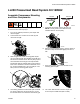

LL250 Pressurized Bead System Kit 16R962
14 332230F
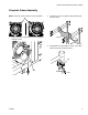
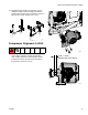
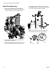
9. Use hardware (shown below) to mount compressor
to compressor bracket. Make certain that the square
of the carriage bolt heads are seated in the com-
pressor bracket slots.
10. Snug all four nuts down then back the nuts off 1/4
turn. Bracket KK should slide in the slots with some
effort.
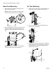
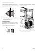
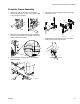
11. Use rubber mallet or wood block to position frame
mount (L) flush to LL250 frame (this location will be
adjusted to help center the compressor with the
drive pulley).
12. Place right frame mount (L) onto LL250 frame in
location shown below (approximately 1 in. from
cross member of LL250 frame). NOTE: To ensure
flush sitting, scrape frame free of any raised debris
on frame surface.
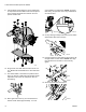
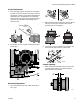
13. Cut any existing tie wraps that interfere (they will be
replaced later with new tie straps).
14. Loosely install two screws (M) and two locknuts (N)
through bottom of frame mount. NOTE: See align-
ment section then use 9/16 in. wrench to fully
tighten.
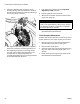
15. Secure hydraulic lines with zip ties.
ti24480a
L
Inches
Centimeter
ti20511a
L
ti20512a
ti20509a
N
M
ti20507a