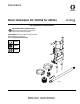
Instructions Direct Immersion Kit 16U764 for 2570ES 332235A EN - For installation of tower/bracket IMPORTANT SAFETY INSTRUCTIONS Read all warnings and instructions in this manual. Save these instructions. 2570ES Models: Refer to operation manual below.
Fixed Mounting (optional) To prevent damaging the unit when transporting it in a truck or on a trailer, Graco recommends fixed mounting to the vehicle. 4. Insert plugs in upper frame handle tubes. upper frame handle tubes Repositioning Handle Before you can secure the unit to a truck or trailer bed, you must reposition the handle. 1. Remove four handle sleeve screws. plugs ti7744b 5. Insert handle into lower frame tubes. Face hose bracket down. Adjust to appropriate in/out location. handle ti7649b 2.
Securing Unit to Vehicle Bed For fixed mounting, fasten U-bolts over sprayer frame as indicated in the following illustration. 1. Reposition handle, steps 1-5, page 2. 2. Place U-bolts over sprayer frame and through holes in vehicle bed. Place a washer and nut over bolt end. Tighten nut securely. Sprayer is a heavy piece of equipment. To avoid bodily injury that could result from equipment moving when transporting, secure sprayer to vehicle. Reposition Handle U-bolts U-bolts 332235A Kit.
General Information Pressure Relief Procedure 4. Turn pressure to lowest setting. 5. Trigger gun to relieve pressure. 6. Turn Prime valve down. 1. Engage trigger lock. 2. Set pump valve OFF. 3. Turn engine OFF. 4 Trigger Lock Engage trigger lock when you stop spraying to prevent gun from being accidentally triggered by hand or if dropped or bumped.
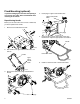
Removing Hydraulic Head and Pump 5. Remove four mounting bolts on pump assembly and set assembly out of the way. pump assembly BURN HAZARD Equipment surfaces and fluid that’s heated can become very hot during operation. To avoid severe burns, do not touch hot fluid or equipment. Wait until equipment/fluid has cooled completely. 1. Follow Pressure Relief Procedure, page 4. bolts 2. Allow unit to cool. 3. Remove two hydraulic lines from head and body. ti7598a hydraulic lines ti20953a 4.
Installing Direct Immersion Kit 1. Install tower/bracket into frame holes. 5. Torque bolts to 400 +/- 10 in-lb (33.3 ft-lb). tower bracket ti7600b frame holes ti7603b 6. Install new, longer hydraulic lines (19, 20) from kit. Pumping motion could result in bracket pulling out of frame and cause serious injury. Always insert and torque screws securely to insure this does not occur. 2. Install four retaining screws in frame to hold tower/bracket in place. Torque to 165 +/- 10 in-lb (13.8 ft-lb).
Using Direct Immersion 4. Unclamp and tilt tower/bracket back to 1st position. MOVING PARTS HAZARD Moving parts can pinch or amputate fingers and other body parts. • Keep clear of moving parts. • Do not operate equipment with protective guards or covers removed. clamp • Pressurized equipment can start without warning. Before checking, moving, or servicing equipment, follow the Pressure Relief Procedure in this manual. Disconnect power or air supply. 1.
7. Install intake tube (24). Lock female hose adapter (22) to hold intake tube securely in place. Verify hose adapter gasket (22a) is in place. Changing Drums 1. Tilt tower/bracket back and clamp securely in 1st position. 22 22a 24 clamp ti21172a 8. Lower intake tube into 55-gallon drum. ti21181a 2. Unlock female hose adapter (22) and remove intake tube (24). ti21173a 22 9. Lock tower/bracket in place. 24 ti21179a 3. Move sprayer/tower/bracket (unit) and align new drum under pump assembly. 10.
4. Ensure gasket (22a) is in place and install intake tube (24). Lock female hose adapter (22) to hold intake tube securely in place. 6. Lock tower/bracket in place. 22 22a 24 7. Ready to use. ti21172 5. Lower intake tube into 55-gallon drum.
Transporting Unit NOTE: Do not transport unit with head in vertical position. When transporting unit securely tie down in vehicle or follow instructions for fixed mounting to vehicle, page 2. 3. Lock in place. 1. Unlock tower/bracket. 2nd position 2. Tip tower/bracket back 90° to 2nd position for transporting.
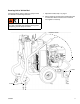
Parts Parts 5 14 34 13 22 10 20 22a 9 19 1 27 4 24 31 15 11 29 3 6 8 28 7 16 17 ti21176a 25 23 Ref 1 2 3 4 5 6 7 8 9 10 11 12 13 14 15 16 17 18 Part Description 287897 SUPPORT, frame 287896 FRAME, 55 gallon lift 188622 SPACER 116630 SCREW 102040 NUT, lock, hex 15H478 PLATE, retainer 112395 SCREW, cap, flnghd 288037 BRACE, tilt, back 119872 SCREW, shoulder 120454 WASHER, flat 15H496 LATCH, liftkit, lower 15H495 LATCH, liftkit, upper 120226 SCREW, hex hd, flange 108063 GRIP, handle 114
Parts Dimensions All dimensions are in inches 80 ti21174a 41 59 ti21175a 78 12 332235A
Notes Notes 332235A 13
Graco Standard Warranty Graco warrants all equipment referenced in this document which is manufactured by Graco and bearing its name to be free from defects in material and workmanship on the date of sale to the original purchaser for use. With the exception of any special, extended, or limited warranty published by Graco, Graco will, for a period of twelve months from the date of sale, repair or replace any part of the equipment determined by Graco to be defective.