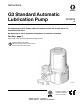
Instructions G3 Standard Automatic Lubrication Pump 332291B EN For dispensing of NLGI Grades #000 to #2 greases and oil with at least 40cSt. For Professional Use Only. Not approved for use in explosive atmospheres or hazardous locations. Part Nos., page 3 5100 psi (35.1 MPa, 351.6 bar) Maximum Working Pressure Important Safety Instructions Read all warnings and instructions in this manual. Save these instructions. TI14705 Conforms to ANSI/UL 73 Certified to CAN/CSA Std. 22.
Contents Part / Model Numbers . . . . . . . . . . . . . . . . . . . . . . . 3 2 Liter Models . . . . . . . . . . . . . . . . . . . . . . . . . . . 3 4 Liter Models . . . . . . . . . . . . . . . . . . . . . . . . . . . 3 8 Liter Models . . . . . . . . . . . . . . . . . . . . . . . . . . . 3 12 Liter Models . . . . . . . . . . . . . . . . . . . . . . . . . . 3 16 Liter Models . . . . . . . . . . . . . . . . . . . . . . . . . . 3 Understanding the Model Number . . . . . . . . . . . 4 Warnings . . . . . . . . .
Part / Model Numbers Part / Model Numbers The Part Number is a six-digit unique number that is only used to order the G3 Pump. Directly related to this six digit Part Number is the configured Graco Model Number. This configured number identifies the distinct features of a specific G3 Pump. To help you understand each component that makes up the Model Number see Understanding Your Model Number, page 4. The tables below shows the relationship between each Part Number and its related Model Number.
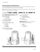
Part / Model Numbers Understanding the Model Number Use the Code Sample provided below to identify each component’s location in the Model Number. The options for each component that make up the code are provided on the lists below. NOTE: Other pump configurations are available that are not documented in this manual. Contact Graco Customer Service or your local Graco distributor for assistance.
Warnings Warnings The following warnings are for the setup, use, grounding, maintenance, and repair of this equipment. The exclamation point symbol alerts you to a general warning and the hazard symbols refer to procedure-specific risks. When these symbols appear in the body of this manual or on warning labels, refer back to these Warnings. Product-specific hazard symbols and warnings not covered in this section may appear throughout the body of this manual where applicable.
Warnings WARNING + SKIN INJECTION HAZARD High-pressure fluid from dispensing device, hose leaks, or ruptured components will pierce skin. This may look like just a cut, but it is a serious injury that can result in amputation. Get immediate surgical treatment. • Do not point dispensing device at anyone or at any part of the body. • Do not put your hand over the fluid outlet. • Do not stop or deflect leaks with your hand, body, glove, or rag.
Installation Installation Grounding The equipment must be grounded. Grounding reduces the risk of electric shock by providing an escape wire for the electrical current in the event of malfunction or breakdown. This product is equipped with a cord having an equipment grounding conductor. The wire with insulation having an outer surface that is green with or without yellow stripes is the grounding wire.
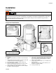
Installation Typical Installation Divider Installations B D E A F Injector Installations E H B D A A Connected to fuse / power B Pressure relief valve (Not included/ required for each outlet user supplied. See Parts, page 30) D Series progressive divider valves (Divider Installations) - Injectors (Injector Installations) E To lube points 8 F G F - Proximity Switch (Divider Installations) - Pressure switch (Injector Installations) G Vent valve (Not included / available from Graco.
Installation Choosing an Installation Location AUTOMATIC SYSTEM ACTIVATION HAZARD If the system is equipped with has an automatic timer (user supplied) that activates the pump lubrication system when power is connected or when exiting the programming function, unexpected activation of the system could result in serious injury, including skin injection and amputation. Before you install or remove the lubrication pump from the system, disconnect and isolate all power supplies and relieve all pressure.
Installation System Configuration and Wiring Fuses NOTICE . Improper installation of the grounding conductor may result in a risk of electric shock. This product must be installed by a qualified electrician in compliance with all state and local codes and regulations. If the product is permanently connected: • it must be installed by a qualified electrician or serviceman. • it must be connected to a grounded, permanent wiring system. Fuses (user supplied) are required on all DC models.
Installation Wiring and Installation Diagrams The following Table identifies the wiring and installation diagrams for the cable included with the pump provided in this manual.
Installation Power DIN AC - 15 foot: Part No. 16U790 Pin and Related Wire Color (FIG. 3) Pin Pin Name 1 2 3 4 Line NEUTRAL Not Used GROUND Color Black White Not Used Green Connector on Housing Connector on Cable (4) (4) (2) (1) (1) (2) (3) Example Wiring Diagram 1 2 3 4 FIG.
Installation Power DIN DC - 15 foot: Part No. 16U790 NOTICE Be sure when power is applied that stirring paddle rotates clockwise (when viewed from the top). If it is wired incorrectly paddle could rotate counter-clockwise which will damage the pump’s internal components. If this happens, stop the pump immediately and wire unit correctly. Pin and Related Wire Color (FIG. 5) Pin Pin Name Color 1 2 3 4 -VDC +VDC Not Used Not Used Black White Not Used Green FIG.
Installation Power CPC DC - 15 foot: Part No. 126217 Pin and Related Wire Color (FIG. 6) Pin Pin Name Color 1 2 3 4 5 6 7 Not Used -VDC +VDC Not Used Not Used Not Used Not Used Not Used Black White Not Used Not Used Not Used Green Connector on Housing Connector on Cable (2) (2) (3) (1) (3) (1) (7) (6) (4) (5) (4) (7) (5) (6) Example Wiring Diagram Ignition Switch Fuse 12V-pump - 7.5A - Graco kit #571039 24V pump - 4A - Graco kit #571040 1 2 3 4 5 6 7 FIG.
Installation Low Level Outputs See Low Level Output Option, page 22 for functional description. See Technical Data, page 32 for ratings. Pin Pin Name 1 2 3 4 Not Used Not Used LL N.O. LL COM Connector on Housing Connector on Housing (4) (4) (3) (1) (1) (2) (3) (2) Example Wiring Diagram 1 2 3 4 G3 FIG.
Installation Part No. 124333: Cable Pin Out (M12) Part No. 124300: Field Wireable Pin Out (M12) Wire Colors Item No. Color 1 2 3 4 Brown White Blue Black Wire Colors Item No. 1 2 3 4 Color Brown White Blue Black FIG. 9 FIG.
Installation Part No. 124594: 4 Pin Eurofast Field Wireable Connector Part No. 124595: 5 Pin Eurofast Field Wireable Connector FIG. 10 332291B FIG.
Setup Setup Connecting to Auxiliary Fittings Pressure Relief Follow the Pressure Relief Procedure whenever you see this symbol. NOTICE Do not attach unsupported equipment to auxiliary fittings such as fill ports and pump element. Attaching unsupported equipment to these fitting can result in irreparable housing damage. This equipment stays pressurized until pressure is manually relieved.
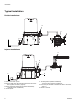
Setup Setting Pump Outlet Volume 3. Tighten pump element fitting. Torque fitting to 50 in. lbs (5.6 N•m). NOTE: • Before making any adjustments to pump volume, Relieve Pressure following procedure on page 18. • Only use Graco supplied spacers to control output volume. • It may be necessary to repeat this outlet volume setup procedure after the pump is operating to re-adjust the volume of dispensed fluids. 1. Use a wrench to turn pump element counter-clockwise to loosen.
Setup Models without a follower plate: For models using an external controller, start pump operation per your controller specifications. 1. Connect fill hose to inlet fitting (FIG. 14). E 3. Fill reservoir with grease until seal of follower plate breaches the vent hole (FIG. 16) and the majority of air is expelled from the reservoir. D vent hole FIG. 14 2. For higher viscosity fluids, start pump to rotate stirring paddle during fill to prevent air pockets from forming in grease.
Setup Filling Oil Unit • Only use oil appropriate for your application, automatic dispensing, and the equipment’s operating temperature. Consult with machine and lube manufacturer for details. • The reservoir can be filled using a hand operated pump, pneumatic pump or electric transfer pump. • Do not overfill (FIG. 17). • Do not operate G3 without reservoir attached. • Only use oils with viscosity at least 40 cSt. FIG. 18 2.
No Controller Operation No Controller Operation The G3 Pump can be controlled using an external, user supplied, power source and controller. Refer to the Typical Installation diagrams provided on page 8 for correct location of the required pump ground wire and fuses. NOTE: • • When using an external power source and controller, Pump ON (Run) Time should be set for no longer than 30 minutes. In most cases, Pump OFF (Rest) Time should be twice as long as Pump ON (Run) time.
No Controller Operation Oil Pumps When the oil level has reached a low warning level, PINS 3 and 4 close, sending the signal to the controller that the fluid has reached a low level. To ensure that a low level condition has been met, the low level trigger must be detected for 10 continuous seconds. See FIG. 21 for an illustration of a typical Low Level Output response to low oil level. Typical Low Level Output Response with Low Level Fluid in Oil Models Closed Contact Position Open FIG.
Troubleshooting Troubleshooting Problem Unit does not power on Unit does not power on (DC models only) Cause Incorrect/loose wiring Solution Refer to Installation instructions, page 7. Tripped external fuse due to internal component failure Contact Graco Customer Service. Tripped external fuse due to pumping non-cold weather lubricant in cold weather -13°F (-25°C) Replace lubricant with pumpable lubricant, rated for environmental conditions and application. Replace fuse.
Maintenance Maintenance Frequency Component Required Maintenance Keep all fittings clean using a clean dry cloth. Dirt and/or debris can damage pump and/or lubrication system. Daily and at refill Zerk Fittings Daily G3 Pump Unit and Reservoir Keep pump unit and reservoir clean using a clean dry cloth. Monthly External Wiring Harness Verify external harnesses are secure.
Parts - 2 Liter Models Parts - 2 Liter Models 40b Follower Plate Models Only Low Level Grease Models Only 40a 43 45 44 35 42 57 27 1 41 16 36 60 23 13 15 Low Level Oil Models Only 12 14 67 18 3 37 21 66 1 33 1 Torque to 4 in. lbs (0.45 N.m) 3 42 26 17 3 2 Torque to 30 in. lbs (3.4 N.m) 3 Torque to 50 in. lbs (5.6 N.
Parts - 4 Liter and Larger Models Parts - 4 Liter and Larger Models Follower Plate Models Only 40a 40b 43 44 Low Level Grease Models Only 41 42 45 36 35 57 27 1 61 16 62 13 14 60 15 12 18 23 Low Level Oil Models Only 3 37 21 33 1 67 17 3 66 1 Torque to 4 in. lbs (0.45 N.m) 3 4 2 2 Torque to 30 in. lbs (3.4 N.m) 3 Torque to 50 in. lbs (5.6 N.
Parts Parts Ref Part 1 Description Qty BASE, three pump housing 1 3 278142 COVER, bottom, with seal 1 4 115477 SCREW, mach, torx pan hd 9 12 127079 13 124396 RECT-RING, included in kit 571042, 571069, 571179 O-RING, 258, included in Kit 571042, 571044, 571045, 571069, 571179 1 15 BEARING, ball 1 17 18 16F368 21 278145 28 PLUG, pump, 3/4-16 27 123025 33 16A579 LABEL, safety 1 1 1 36 1 1 LABEL, brand 123741 40a 24E984 1 40b 16G021 1 40a 24B702 1 2 1 WIPER, stirrin
Parts Ref 40a 40b 40a 40a 41 42 43 44 45† † † † † 57 Part Description RESERVOIR, 8 liter, grease, 96G039, 96G041, 96G043, 96G045, 96G049, 96G056, 96G187 RESERVOIR, 8 liter, oil, 96G052, 96G061, included in Kit 571182 RESERVOIR, 12 liter, 96G057, 96G077, 96G171 RESERVOIR, 16 liter, 96G058, 96G172 SEAL, follower plate, 2 liter models 278139 96G006, 96G008 SEAL, follower plate, 4 liter models 16F472 96G053, 96G062, 96G179 PLATE, follower, 2 liter models 96G006, 96G008 PLATE, follower, 4 liter mod
Parts Ref Part 124300 201 124333 124301 202 124594 124595 Description Qty CABLE, M12, 15 ft., 4 wire, straight male to flying leads (See Wiring Diagram, page 16) CABLE, M12, 15 ft., 4 wire, straight male to female (See Wiring Diagram, page 16) CONNECTOR, Eurofast, fem, straight, 4 Pin CONNECTOR, Eurofast, 4 Pin (see wiring diagram, page 17) CONNECTOR, Eurofast, 5 Pin (see wiring diagram, page 17) 1 1 1 1 1 Replacement Danger and Warning labels, tags and cards are available at no cost.
Parts Installation and Repair Kits Kit No.
Technical Data Technical Data Maximum Working Pressure 5100 psi (35.1 MPa, 351.6 bar) Power 100-240 VAC 88 - 264 VAC; 0.8 A current, 90 VA Power, 47/63 Hz, Single phase, inrush/locked rotor, max 40A (1ms) 12 VDC 9 - 16 VDC; 5 A current, 60 W, inrush/locked rotor 12 A 24 VDC 18 - 32 VDC; 2.5 A current, 60 W, inrush/locked rotor 6 A Outputs - Low Level (Dry Contact) Contact Rating 10 Watts Maximum Switch Rating 200 VDC Maximum Switching Current 0.5 A Maximum Carry Current 1.
Technical Data Mounting Pattern (For correct mounting configuration, choose either Option 1 or Option 2). See P/N 126916 template. Option 1 0.367inch 9.3 mm 7.087 inch 180.0 mm 2x Ø 0.366 inch 9.3 mm 1.180 inch 30.0 mm 3.268 inch 83.0 mm 3.544 inch 90.0 mm Option 2 0.722 inch 18.3 mm 6.378 inch 162.0 mm 2x Ø 0.366 inch 9.3 mm 0.708 inch 18.0 mm 3.740 inch 95.0 mm 3.189 inch 81.0 mm FIG.
Graco Standard Warranty Graco warrants all equipment referenced in this document which is manufactured by Graco and bearing its name to be free from defects in material and workmanship on the date of sale to the original purchaser for use. With the exception of any special, extended, or limited warranty published by Graco, Graco will, for a period of twelve months from the date of sale, repair or replace any part of the equipment determined by Graco to be defective.