Instructions G1™ Plus Lubrication Pump 332317C EN For dispensing of NLGI Grades #000 to #2 greases and oil with at least 40cSt. For Professional Use Only. Not approved for use in explosive atmospheres or hazardous locations. Part Nos., page 3 5100 psi (35.1 MPa, 351.6 bar) Maximum Working Pressure Important Safety Instructions Read all warnings and instructions in this manual. Save these instructions. 3132066 conforms to ANSI/UL 73 certified to CAN/CSA Std. 22.
Table of Contents Table of Contents Grease Models . . . . . . . . . . . . . . . . . . . . . . . . . . . . . 3 Oil Models . . . . . . . . . . . . . . . . . . . . . . . . . . . . . . . . 4 Warnings . . . . . . . . . . . . . . . . . . . . . . . . . . . . . . . . . 5 Installation . . . . . . . . . . . . . . . . . . . . . . . . . . . . . . . . 7 Grounding . . . . . . . . . . . . . . . . . . . . . . . . . . . 7 Component Identification . . . . . . . . . . . . . . . 7 Typical Installation . . . . . . . . . . . .
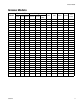
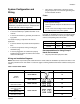
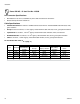
Grease Models Grease Models Reservoir Size Model 94G000 100-240 2 Liter 4 Liter 8 Liter 12V DC 24V DC VAC X 94G001 X 94G002 94G003 X X 94G004 X 94G005 94G012 X X 94G013 X 94G014 94G015 X X 94G016 X 94G017 94G024 X X 94G025 X 94G026 94G027 X X 94G028 X 94G029 94G048 X X 94G049 X 94G050 94G051 X X 94G052 X 94G053 94G054 94G055 94G056 332317C Voltage X X X X CPC DIN Wiper Follower Low Level X X X X X X X X X X X X X X X X X X X X X X X X X X X
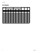
Oil Models Oil Models Reservoir Size Model 94G030 100-240 2 Liter 4 Liter 8 Liter 12V DC 24V DC VAC X 94G031 X 94G032 94G033 X X 94G034 X 94G035 94G057 X X 94G058 X 94G059 94G060 94G061 94G062 4 Voltage X X X X CPC DIN Low Level X X X X X X X X X X X X X X X X X X X X X X X X X X X X X X 332317C
Warnings Warnings The following warnings are for the setup, use, grounding, maintenance, and repair of this equipment. The exclamation point symbol alerts you to a general warning and the hazard symbols refer to procedure-specific risks. When these symbols appear in the body of this manual or on warning labels, refer back to these Warnings. Product-specific hazard symbols and warnings not covered in this section may appear throughout the body of this manual where applicable.
Warnings WARNING SKIN INJECTION HAZARD High-pressure fluid from dispensing device, hose leaks, or ruptured components will pierce skin. This may look like just a cut, but it is a serious injury that can result in amputation. Get immediate surgical treatment. • Do not point dispensing device at anyone or at any part of the body. • Do not put your hand over the fluid outlet. • Do not stop or deflect leaks with your hand, body, glove, or rag.
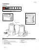
Installation Installation Grounding The equipment must be grounded. Grounding reduces the risk of electric shock by providing an escape wire for the electrical current in the event of malfunction or breakdown. Component Identification K H J Oil Models Grease Models Grease Models with Follower Plate A E C D F B G L FIG.
Installation Typical Installation B C D A A B Connected to fuse / power Pressure relief valve (required, user supplied) C D Series progressive divider valves To lube points Choosing an Installation Location AUTOMATIC SYSTEM ACTIVATION HAZARD Unexpected activation of the system could result in serious injury, including skin injection and amputation. This device has an automatic timer that activates the pump lubrication system when power is connected or when exiting the programming function.
Installation System Configuration and Wiring • when repair or replacement of the power cord or plug is required, do not connect the grounding wire to either flat blade terminal. Fuses . Improper installation of the grounding conductor may result in a risk of electric shock. This product must be installed by a qualified electrician in compliance with all state and local codes and regulations. If the product is permanently connected: • it must be installed by a qualified electrician or serviceman.
Installation Power DIN AC - 15 foot: Part No. 123358 Din Connector Specifications • • DIN 43650 Form A, 18 mm, assembled to power cable manufacturer’s instructions Rated to 6 Amps minimum at 250V AC Cable Specifications • United States/Canada: 3 conductor 16 AWG UL62 and CSA 22.2 No. 49 listed SOOW cable with black, white, green insulation • Europe: 3 Class-5 conductor, 1.5 mm2 Agency Listed H07RN-F cable with blue, brown, green/yellow insulation • Japan/Taiwan: 3 conductor, 1.
Installation Connector on Housing Connector on Cable (4) (4) (2) (1) (1) (2) (3) Example Wiring Diagram 1 2 3 4 FIG.
Installation Power DIN DC - 15 foot: Part No. 123358 NOTICE Be sure when power is applied that stirring paddle rotates clockwise (when viewed from the top). If it is wired incorrectly paddle could rotate counter-clockwise which will damage the pump’s internal components. If this happens, stop the pump immediately and wire unit correctly.
Installation Connector on Cable Connector on Housing (4) (4) (2) (1) (1) (2) (3) Example Wiring Diagram Ignition Switch Fuse 1 2 3 4 12V-pump - 7.5A - Graco kit #571039 24V pump - 4A - Graco kit #571040 FIG.
Installation Power CPC DC - 3-Wire, 15 foot: Part No. 126217 CPC Connector Specifications • • • One, 7-position, 1.5 mm socket connector AMP 967650-1 Three, 16 - 14 gauge female pins AMP 962999-1 One, 180-degree strain relief or one, 90-degree strain relief AMP 965576-1 (determined by cable exit for cable configuration) Installation Notes • • • Crimp pins to wire and install in socket connector per manufacturer’s instructions. See Pin Layout shown in FIG. 4 for proper location in the connector.
Installation Connector on Housing Connector on Cable (2) (2) (3) (1) (3) (1) (7) (6) (4) (5) (4) (7) (5) (6) Example Wiring Diagram Ignition Switch Fuse 12V-pump - 7.5A - Graco kit #571039 24V pump - 4A - Graco kit #571040 1 2 3 4 5 6 7 FIG.
Installation Power CPC DC - 5 wire Part No.: 123750: 15 ft (4.5 m) Part No.: 126219: 20 ft (6.1 m) Part No.: 126220: 30 ft (9.1 m) NOTE: An Illuminated Remote Run Button Kit: 571030, 571031 for starting a manual run cycle remotely if used in conjunction with a 5-wire CPC cable, is available from Graco. Contact your local Graco distributor or Graco Customer Service for additional information about these kits. CPC Connector Specifications • • • One, 7-position, 1.
Installation Connector on Cable Connector on Housing (2) (2) (3) (1) (3) (4) (7) (1) (6) (4) (7) (5) (5) (6) Example Wiring Diagram Fuse 12V-pump - 7.5A - Graco kit #571039 24V pump - 4A - Graco kit #571040 L 1 2 3 4 5 6 7 FIG.
Setup Setup Connecting to Auxiliary Fittings Pressure Relief Follow the Pressure Relief Procedure whenever you see this symbol. NOTICE Do not attach unsupported equipment to auxiliary fittings such as fill ports and pump element. Attaching unsupported equipment to these fitting can result in irreparable housing damage. This equipment stays pressurized until pressure is manually relieved.
Setup Loading Grease 3. Fill reservoir with NLGI grease to max fill line. To ensure optimal performance from the G1: NOTE: Vent port, located in rear of reservoir, should not be used as an overfill port/indicator. • Only use NLGI #000 - #2 greases appropriate for your application, automatic dispensing, and the equipment’s operating temperature. Consult with machine and lube manufacturer for details. • The reservoir can be filled using a hand operated pump, pneumatic pump or electric transfer pump.
Setup Priming Changing Greases When changing greases, always use compatible fluids or greases. Pump only requires priming the first time it is used or if it is allowed to run dry. Filling Oil Unit • NOTE: It is not necessary to prime pump every time pump is filled with lubricant. Only use oil appropriate for your application, automatic dispensing, and the equipment’s operating temperature. Consult with machine and lube manufacturer for details.
Plus Model Control Setup Plus Model Control Setup Control Panel Overview (FIG. 13) NOTE: Programming instructions begin on page 22. OFF TIME • ON TIME • • • • • • • • The blinking LED below ON indicates the ON Time sequence is running. Display shows time as MM (minutes). i.e., 02 is 2 minutes. Times lubrication cycle. Counts down from a set time to zero. The blinking LED below OFF indicates the OFF Time sequence is running. Value is entered in HH. Displays in HH. Times pump rest between cycles.
Plus Model Control Setup Instructions Entering a PIN Code to Access Setup Mode Powering Units With Controllers By default, units with controllers are set to operate in a timed mode with 1 minute of ON time and 8 hours of OFF time. The unit should be powered up in OFF mode, counting down from the 8 hours. If the unit powers up in ON mode and has not been primed, hold the reset button located on the control panel (example shown on the right) for 1 second to move to the OFF mode.
Plus Model Control Setup ON Time OFF Time • ON Time is set in Minutes (MM). • OFF Time is set in Hours (HH). • In SETUP MODE, the number displayed in the first field, on the left side of display blinks, indicating the device is ready to program the ON Time minutes. • In SETUP MODE the number displayed in the first field, on the left side of display blinks, indicating the device is ready to program the OFF Time hours. • The total amount of ON Time cannot exceed 30 minutes.
Advanced Programming Advanced Programming Advanced Option Setting Format/ Description A1 Lockout Code (Optional) Secures setup modes with PIN Why Use This? Prevents unauthorized users to adjusting settings. Entering a PIN Code for the First Time Entering Advanced Setup Setting Up PIN Code Press the UP ARROW button for 10 seconds. A PIN Code can be programmed into the G1 to protect the settings from inadvertently being changed by unauthorized users. 1. Press the UP ARROW button for 10 seconds.
Run Mode Run Mode Low Level Pumps equipped with low level detection will stop when the fluid level is sufficiently low to trigger the low level fault. Time Control After setup is complete, the G1 automatically begins to run the OFF Time sequence. • The G1 runs the programmed OFF sequence. ON • Add lubricant to the pump. See Loading Grease instructions, page 19 or Filling Oil Unit, page 20. OFF • (Notice the dot below OFF flashes on the display MM while the OFF Time counts down.
Troubleshooting Troubleshooting Problem Unit does not power on Cause Solution Incorrect/loose wiring Refer to Installation instructions, page 7. Tripped external fuse due to internal component failure Contact Graco Customer Service. Unit does not power on (DC models only) Tripped external fuse due to pumping non-cold weather lubricant in cold weather -13°F (-25°C) Replace lubricant with pumpable lubricant, rated for environmental conditions and application. Replace fuse.
Maintenance Maintenance Frequency Component Required Maintenance Daily and at refill Zerk Fittings Keep all fittings clean using a clean dry cloth. Dirt and/or debris can damage pump and/or lubrication system. Daily G1 Pump Unit and Reservoir Keep pump unit and reservoir clean using a clean dry cloth. Daily Display Keep display clean using a clean dry cloth. Monthly External Wiring Harness Verify external harnesses are secure.
Parts: 2 Liter Models Parts: 2 Liter Models Oil Reservoir 43 40b 44 42 Low Level Grease Models Only 45 35 41 Follower Plate Models Only 57 271 23 40a 60 15 16 13 67 14 13 3 37 1 66 31 17 3 Low Level Oil Models Only 33 1 Torque to 4 in. lbs (0.45 N.m) 2 Torque to 30 in. lbs (3.4 N.m) 34 3 Torque to 50 in. lbs (5.6 N.
Parts: 4 and 8 Liter Models Parts: 4 and 8 Liter Models Oil Reservoir 43 41 40b 44 Low Level Grease Models Only 41 45 42 Follower Plate Models Only 35 57 40a 271 23 60 61 16 13 62 67 13 14 13 66 3 37 1 31 Low Level Oil Models Only 33 17 3 1 Torque to 4 in. lbs (0.45 N.m) 2 Torque to 30 in. lbs (3.4 N.m) 3 Torque to 50 in. lbs (5.6 N.
Parts Parts FN 1 3 4 13 14 Part No. Description BASE, molded 278142 BOTTOM, cover 115477 SCREW, bottom cover O-RING, 258 (green), included in Kit 124396 571042, 571043, 571044, 571045, 571069, 571179 O-RING, included in Kit 571069, 124510 571179, 571182, 571183 PLATE, ricer 15 BEARING, ball 16 17 Qty. 1 1 9 FN Part No. Description Qty.
Parts Pressure Relief Valves Fuses Important Information regarding Pressure Relief Valve 16C807. Part Pressure Relief Valve 16C807 can only be used on the G1 and G3 Pumps. It is not intended for use with any other products. The pressure relief valve uses a pressure adjustment screw (a) to set the pressure release point. It is not intended as a way to relieve pressure during normal operation, but as a protective measure in the event there is an unintended pressure increase in the system.
Technical Data Technical Data A Maximum Working Pressure Power 100-240 VAC 5100 psi (35.1 MPa, 351.6 bar) 88 - 264 VAC; 0.8 A current, 90 VA Power, 47/63 Hz, Single phase, inrush/locked rotor, max 40A (1ms) 9 - 16 VDC; 5 A current, 60 W, inrush/locked rotor 12 A 18 - 32 VDC; 2.
Technical Data Mounting Pattern For correct mounting configuration, choose either Option 1 or Option 2. See P/N 126916 template. Option 1 0.367inch 9.3 mm 7.087 inch 180.0 mm 2x Ø 0.366 inch 9.3 mm 1.180 inch 30.0 mm 3.268 inch 83.0 mm 3.544 inch 90.0 mm Option 2 0.722 inch 18.3 mm 6.378 inch 162.0 mm 2x Ø 0.366 inch 9.3 mm 0.708 inch 18.0 mm 3.740 inch 95.0 mm 3.189 inch 81.0 mm FIG.
Graco Standard Warranty Graco warrants all equipment referenced in this document which is manufactured by Graco and bearing its name to be free from defects in material and workmanship on the date of sale to the original purchaser for use. With the exception of any special, extended, or limited warranty published by Graco, Graco will, for a period of twelve months from the date of sale, repair or replace any part of the equipment determined by Graco to be defective.