Kit Instructions ExactaBlend™ AGP Advanced Glazing Proportioner Accessory Kits 332453C EN For dispensing two component silicone and urethane materials. For professional use only. Not approved for use in explosive atmospheres or hazardous locations. Refer to ExactaBlend AGP Advanced Glazing Proportioner, Setup-Operation manual for maximum working pressure and model information.
Related Manuals Related Manuals Refer to ExactaBlend AGP Advanced Glazing Proportioner, Setup-Operation manual for the complete list of related manuals. Contents Related Manuals . . . . . . . . . . . . . . . . . . . . . . . . . . . 2 Contents . . . . . . . . . . . . . . . . . . . . . . . . . . . . . . . . . . 2 Installation . . . . . . . . . . . . . . . . . . . . . . . . . . . . . . . . 3 Light Tower, 24R824 . . . . . . . . . . . . . . . . . . . . . . 3 S100 Low Level Sensors, 24R935 . . . . . . . . . . .
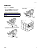
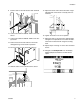
Installation Installation Light Tower, 24R824 4. Mount the light tower to the bracket. Hand tighten the light tower nut. 1. Perform the Shutdown procedure in the ExactaBlend AGP Advanced Glazing Proportioner, Setup-Operation manual. 2. Remove the rear nut that secures the fluid plate. NOTICE To avoid machine damage or injury, do not remove both bolts. 5. Connect the cable from the light tower to port 5 located on the Fluid Control Module (FCM). 3. Fasten the light tower bracket to the boom assembly.
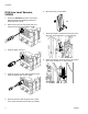
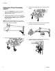
Installation S100 Low Level Sensors, 24R935 1. Perform the Shutdown procedure in the ExactaBlend AGP Advanced Glazing Proportioner, Setup-Operation manual. 6. Mount the sensor to the bracket. x2 2. Remove the air shut off valve cable from port 1 located on the Fluid Control Module (FCM). 7. Attach the bracket to the electrical enclosure for the base ram. Torque the bolts to 5.1 ft-lb (6.9 N•m). 3. Install the splitter into port 1. 8. Attach the bracket to the pump mast for the catalyst ram.
Installation 9. Install a collar on the mast shaft for both chemical rams. 10. Connect the cable end labeled “J1BA” to the base sensor. 11. Connect the cable end labeled “J1BB” to the catalyst sensor. 12. Route and secure access cable so it will not be damaged during normal machine operation. 13. Turn the power on at the electrical enclosure. 15. Adjust the sensor until it senses the collar. A light will aluminate on the sensor to visually show it is activated. 16.
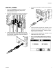
Installation Calibration Check Assembly, 24R777 4. Install the tube fittings. Tighten the fittings to prevent leaking. 1. Perform the Shutdown procedure in the ExactaBlend AGP Advanced Glazing Proportioner, Setup-Operation manual. 2. Install the hose clamps onto the boom assembly. Hand tighten all hose clamps. Refer to Calibration Check Assembly, 24R777, page 14, for correct screw locations. NOTE: The base material tube is 0.5 in. (1.3 cm) in diameter.
Installation USB Kit, 24R936 4. Connect the CAN cable to the Fluid Control Module (FCM). 1. Perform the Shutdown procedure in the ExactaBlend AGP Advanced Glazing Proportioner, Setup-Operation manual. 2. Mount the USB Module to the side of the electrical enclosure. Torque the bolts to 2.6 ft-lb (3.5 N•m). 5. Install the software upgrade token (16V853) into the Display Module (DM) and cycle the power. Refer to the Graco Control Architecture™ Module Programming manual for more details. 3.
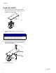
Installation Caster Kit, 24T091 1. Mount the caster to the bracket. Apply medium strength thread locker to the threads. Torque the fasteners to 21 ft-lb (29 N•m). x4 2. Lift the machine until it is 3 in. (8 cm) off of the ground. NOTICE Injury may occur if the machine is lifted and not secured to prevent falling. Rest the machine on stands or blocks while installing the caster kit. 3. Fasten the bracket to the base frame. Apply medium strength thread locker to the threads.
Operation Operation USB Kit, 24R936 Run Data When a USB memory device is inserted into the USB module, a status icon will appear on the DM screen. The icon will appear as shown when downloading is complete. This file shows the date, time, target ratio, actual ratio, average flow rate, and both pump A and pump B chemical dispenses. All chemical dispense values are shown in kilograms. The information is recorded at 5 second intervals.
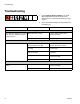
Troubleshooting Troubleshooting 1. Follow Pressure Relief Procedure in the ExactaBlend AGP Advanced Glazing Proportioner, Setup-Operation manual before checking or repairing gun. 2. Check all possible problems and causes before disassembling gun. Problem Cause Solution Light Tower Light does not blink green, red, and off in sequence when the machine is first turned on. Bad connection or cable Ensure cable is connected or replace the cable. Bad light stack. Replace light stack.
Troubleshooting 332453C 11
Parts Parts Light Tower, 24R824 3 1 2 FIG. 1: Light Tower Ref 1 2 Part --127187 Description BRACKET, tower, light, 30mm LIGHT, tower, 30mm, red / green / alarm 3 127184 HARNESS, m12xm12 Quantity 1 1 1 --- Not available for individual sale.
Parts S100 Low Level Sensors, 24R935 102 106 109 103, 105 101 103, 105 110 101 108 106 102 103, 105 FIG.
Parts Calibration Check Assembly, 24R777 208, 211, 223 213 212 214 208, 211, 223 215 216 217 209, 210, 211 209, 210, 211 208, 222 209, 223 201 204 218, 219, 220 206 FIG. 3: Calibration Check Assembly Ref 201 204 206 208 209 210 211 212 Part --127071 127070 126691 126682 --122643 16V586 Description MODULE, ratio check, FITTING, flareless, 1/2 npt x 1/2 tube FITTING, flareless, 1/4 npt x 1/4 tube CLAMP, 1/2 in. od hose CLAMP, 1/4 in.
Parts Calibration Check Module 306 1 305 1 303 302 304 1 301 307 309 303 313 301 1 306 307 308 1 Apply sealant to pipe threads. 312 FIG.
Parts USB Kit, 24R936 401, 402 403 404 FIG. 5: USB Kit Ref 401 402 403 Part 24T005 --16T072 Description MODULE, GCA, cube SCREW, socket head, 10-32x0.75 ADAPTER, cable, CAN, IS to non IS 404 120952 CABLE, CAN, female / female 4.
Parts Caster Kit, 24T091 1 Apply medium strength thread locker to threads. 2 Torque to 30 ft-lb (40 N•m). 3 Torque to 21 ft-lb (29 N•m). 504 1 2 501 502, 503 1 2 506 1 3 505 FIG. 6: Caster Kit Ref 501 502 503 Part ------- Description BRACKET, caster BOLT, carriage, M10-1.5x30mm NUT, hex, flange, serrated, M10-1.5 Quantity 4 8 8 504 --- SCREW, machine, hex, M10-1.5x25mm 4 505 --- CASTER, swivel, brake 4 506 --- SCREW, cap, hex head, M8-1.25x16mm 16 --- Not available for individual sale.
Graco Standard Warranty Graco warrants all equipment referenced in this document which is manufactured by Graco and bearing its name to be free from defects in material and workmanship on the date of sale to the original purchaser for use. With the exception of any special, extended, or limited warranty published by Graco, Graco will, for a period of twelve months from the date of sale, repair or replace any part of the equipment determined by Graco to be defective.