Instructions-Parts Color/Catalyst Dispense 332454B Valves EN To dispense color, catalyst, and solvent in a ProMix® PD2K Electronic Proportioning System with the color change option. For professional use only. Important Safety Instructions Read all warnings and instructions in your color change kit manual and PD2K proportioner manual. Save these instructions. See page 3 for model part numbers and maximum working pressures. PROVEN QUALITY. LEADING TECHNOLOGY.
Contents Related Manuals ................................................ 2 Models............................................................... 2 Repair................................................................ 3 Disassembly ................................................ 3 Reassembly ................................................ 4 Low Pressure Valve Parts ............................ 5 High Pressure Valve Parts............................ 6 O-Ring Size Guide ...................................
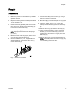
Repair Repair Disassembly 1. Relieve the pressure as described in your PD2K operation manual. 7. Unscrew the ball (3) from the shaft (4), using a wrench on the flats of the ball. 2. Remove the valve from the manifold as described in your color change kit manual. Inspect the 111450 manifold o-ring. 8. Slide the piston and shaft assembly (4) out of the seat housing (2). Remove the piston o-ring (18). 3. Hold the seat body (2) steady with a box wrench.
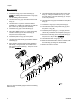
Repair Reassembly 1. Install the o-rings (15) on the seat body (2). NOTE: Circulating valves have three o-rings (15); non-circulating valves have two. 2. Lubricate the o-ring (14) and install it in the seat body (2). 3. Lubricate the u-cup in the seal and retainer assembly (7). Install in the seat body (2) with the lips of the u-cup facing into the seat body. 4. Install the o-ring (19) in the seat body (2). 5. Using the 16N257 Tool (111), screw the backup seal and washer (9) into the seat body (2).
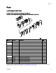
Parts Parts Low Pressure Valve Parts Part No. 24T442 Low Pressure Circulating Valve (shown) Part No. 24T441 Low Pressure Non-Circulating Valve (see detail at upper left) Ref. No. Part No.
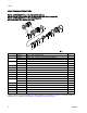
Parts High Pressure Valve Parts Part No. 24T582 High Pressure Circulating Valve (shown) Part No. 24T581 High Pressure Non-Circulating Valve (see detail at upper left) Part No. 24T583 High Pressure Non-Circulating Acid Compatible Valve (see detail at upper left) Ref. No. Part No.
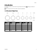
Parts O-Ring Size Guide The following illustrations show the valve o-rings at actual size. See the Parts drawings for locations of the o-rings. TIP: Some o-rings are close in size. Stack on a bench to differentiate. Kit 24T847, for Low Pressure Valves Figure 3 Kit 24T847 O-Ring Sizes Ref. No. Part No. Nominal Size OD, in. (mm) Qty ——— 111450 010 0.4 (10) 1 14* 113746 014 0.6 (16) 1 15* 117559 020 1 (25) 3 16* 121370 022 1.1 (29) 2 18* 116768 016 0.
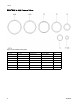
Parts Kit 24T848, for High Pressure Valves Figure 4 Kit 24T848 O-Ring Sizes Ref. No. Part No. Nominal Size OD, in. (mm) Qty ——— 111450 010 0.4 (10) 1 14* 113746 014 0.6 (16) 1 15* 16N901 025 1.3 (33) 3 16* 122134 027 1.4 (37) 2 18* 16V699 021 1.06 (27) 1 19* 117517 015 0.7 (18) 1 20* 16D531 023 1.
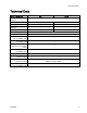
Technical Data Technical Data U.S. Metric Low pressure valves 300 psi 2.1 MPa, 21 bar High pressure valves 1500 psi 10.5 MPa, 105 bar 100 psi 0.7 MPa, 7.0 bar 85–100 psi 0.6–0.7 MPa, 6.0–7.
Graco Standard Warranty Graco warrants all equipment referenced in this document which is manufactured by Graco and bearing its name to be free from defects in material and workmanship on the date of sale to the original purchaser for use. With the exception of any special, extended, or limited warranty published by Graco, Graco will, for a period of twelve months from the date of sale, repair or replace any part of the equipment determined by Graco to be defective.