
User's Manual

Setup the Module
s
Setup IS Contr
ol Modules
NOTE: Two color change control modules may be
installed in the hazardous area. The modules are
labeled 7 or 8. An alternate label is provided with
the module kit for Module 8 (Colors 13–30). Affix the
label according to your system configuration.
Configure eac
h module according to its designated
number, as f
ollows:
NOTICE
To avoid dam
aging the circuit boards, wear Part
No. 112190
grounding strap on your wrist and
ground app
ropriately.
To avoid electrical component damage, remove all
system power before plugging any connectors.
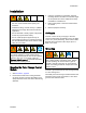
1. Remove electrical power from the system.
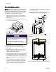
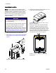
2. Open the color change module. Locate switches
S4, S5, and S6 on the control module board. The
switches may be shipped in the OFF position.
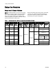
3. For each module, set the switches to ON or OFF,
as shown in the following table.
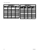
IS Control Mod
ule Switch Settings
Control
Module
S6 S5 S4
Module 7
OFF
ON
OFF
ON
OFF
ON
Module 8
OFF
ON
OFF
ON
OFF
ON
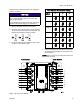
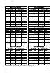
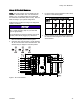
4. Use the following figure and tables to determine
the solenoid valve assigned to each valve in the
valve manifold.
Figure 4 IS Control Module
332455F 15