
User's Manual

Installation
Non-Hazardous Location
NOTE: Non-IS c
olor change control modules provide
control for th
e pump’s inlet and outlet color/catalyst
change valves
. Depending on the number of valves
in the system,
as many as six control modules may
be installed
in the non-hazardous location.
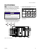
1. Mount the first non-IS color control module as
described in Mounting the Color Change Control
Module, page 17.
2. Connect the 5–pin CAN cable (109) to J7 on the
color control module (108).
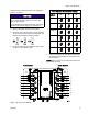
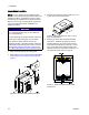
Figure 5 Cable Connector J7 at Non-IS Color
Control Module
NOTICE
To avoid damaging the circuit boards, wear
Part No. 112190 grounding strap on your wrist
and ground appropriately.
To avoi
d electrical component damage,
remove
all system power before plugging any
conne
ctors.
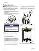
3. Remove electrical power from the system.
4. Remove the cover from the PD2K electrical
control box.
5. Install the supplied 2–cable grommet (110) on
the cable (109) and secure the grommet to the
side of the electrical control box.
6. Connect the cable (109) to J2 on the non-IS side
of the isolation board inside the electrical control
box. See Electrical Schematics, page 34 for a list
of M12 CAN cables for use in a non-hazardous
area.
7. To install additional color control modules (six
maximum), mount the module(s) as described
in Mounting the Color Change Control Module,
page 17. Connect a 5–pin CAN cable from J11
of the previou
s color control module to J7 of the
next control m
odule.
8. Replace the co
ver of the PD2K electrical control
box before tur
ning on power to the system.
Figure 6 Cable Connection at PD2K Electrical
Control Box
Figure 7 Detail of Isolation Board Cable Connections
18 332455F