
User's Manual

Installation
Hazardous Location
NOTE: IS color
change control modules provide
control for co
lor/catalyst change valves located in the
hazardous loc
ation. A maximum of two IS control
modules may be
installed in the hazardous location.
See IS Color C
hange Control Modules, page 62 for
alistofmodu
les approved for installation in a
hazardous lo
cation.
NOTICE
To avoid dam
aging the circuit boards, wear Part
No. 112190 g
rounding strap on your wrist and
ground appr
opriately.
To avoid electrical component damage, remove all
system power before plugging any connectors.
Only approved cables may be used in the
hazardous location. Hazardous location cables are
marked with a light blue flag next to each connector.
See Optional Cables and Modules, page 40 for a
list of M12 CAN cables for use in a hazardous area.
1. Remove electrical power from the system.
2. Mount the first color control module as described
in Mounting the Color Change Control Module,
page 17.
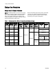
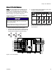
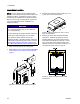
Figure 8 Intrinsically Safe Cable Connections
3. Connect the ha
zardous location cable (C1) to J7
on the color co
ntrol module (108).
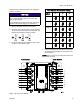
Figure 9 Cable Connectors J7 and J11 at IS
Color Control Module
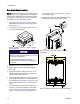
4. Remove the cover from the PD2K electrical
control box. Install the grommet (G) on the
supplied cable (C1) and secure the grommet
to the side of the electrical control box. Locate
J4ontheISsideoftheisolationboardinthe
electrical control box. Connect the cable (C1) to
J4. See Electrical Schematics, page 34.
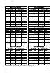
Figure 10 Detail of Isolation Board Cable
Connections
20 332455F