
User's Manual

Installation
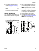
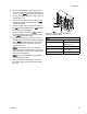
5. Mount a second color control module as
described in Mounting the Color Change
Control Module, page 17. Connect the supplied
hazardous location cable (C2) from J11 on the
first color control module to J7 on the second
module.
6. Replace the cover of the PD2K electrical control
box before turning on power to the system.
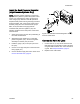
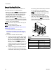
Install the
Valve Manifolds
NOTE: Always label the color connections to prevent
cross-connections. Label the inlet manifold, outlet
manifold, and each color valve with its assigned color.
The solvent and dump valves should be furthest from
the manifold stack primary inlet or outlet.
1. Install a m
ounting bracket (101) on the PD2K
with four
screws (103). High pressure systems:
For stabi
lity, be sure to fasten the bottom screws
(103) to t
he pump bracket.
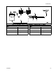
2. Install the inlet and outlet valve manifolds (102)
on the mounting bracket (101) with four screws
(104), washers (105), and nuts (106).
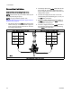
NOTE: On low pressure systems, the supplied
bracket (101) will accommodate a manifold
with 16 valve positions (14 colors). On high
pressure systems, the supplied bracket (101) will
accommodate a manifold with 14 valve positions
(12 colors). A larger valve stack will require a
customer supplied/sourced bracket.
3. Repeat for the opposite side of the PD2K.
4. Connect the air lines from the solenoids to the
valves. See Connect the Valve Air Lines, page 23.
NOTE: On high pressure systems, see
Install the Back Pressure Regulator (High
Pressure Systems Only), page 23.
5. Connect the fluid supply lines to the valves. See
Connect the Fluid Lines, page 24.
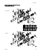
Figure 11 Install the Valve Manifolds
332455F
21