
User's Manual

Installation
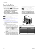
6. Connect a dedicated gun supply line for each
color to the corresponding color valve fitting (C1,
C2, etc.) on the outlet color valve stack. Connect
theotherendofthislinetotheAsideofthemix
manifold at the gun.
7. Connect the supply line for each catalyst to the
corresponding catalyst valve fitting on the inlet
catalyst valve stack.
8. Connect a supply line from the bottom fitting of
the inlet catalyst valve stack to the inlet manifold
of the material B dosing pump.
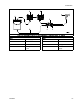
9. Connect a supply line from the outlet manifold of
the material B dosing pump to the bottom fitting
of the outlet catalyst valve stack.
10. Connect a dedicated gun supply line for each
catalyst to the corresponding catalyst valve fitting
on the outlet catalyst valve stack. Connect the
other end of this line to the B side of the mix
manifold at the gun.
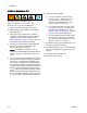
NOTE: If your system uses more colors than
catalysts, branch the catalyst line to connect it to
each mix manifold. Install a check valve on each
branch of the catalyst line.
NOTE: For ease of maintenance, install a ball
valve at all fluid line tees.
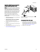
11. The mix manifold is belt-mounted. Connect a
fluid hose between the manifold outlet and the
gun inlet.
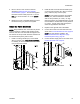
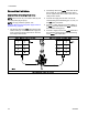
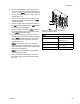
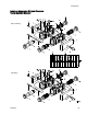
Figure 13 Color Change Connections
(Non-Circulating System)
KEY
A Air inlet
W
Seal weep and
lubrication port
S Solvent fitting
C1 Color 1 fi
tting
C2 Color 2 fitting
332455F 25