Installation
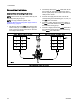
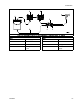
Fluid Flow Schematic Diagram in Circulating Mode (Pump Not Shown for Clarity)
KEY
A
Color supply
B Inlet color stack
C Outlet color stack
D
Y fitting at mix manifold
Aport
KEY
E
Fluid shutoff valve
F
Mix manifold
G Spray gun
H
Returnlinetofluid
supply
332455F
27