
User's Manual

Installation
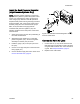
Install an Expansion Kit
Expansion Kits are available to add
valves or manifolds to your system. See
Expansion Kits, page 64 for available kits.
1. Remove elect
rical power from the system.
2. Relieve pres
sure as described in your PD2K
Operation M
anual.
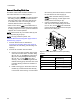
3. Open the con
trol module cover. Install the
solenoid(s
) and air fitting(s) at the appropriate
position(
s) in the solenoid manifold. See
Setup the M
odules, page 12. Connect one end
of the tubi
ng to the solenoid’s air fitting.
4. Connect th
e solenoid wires to the appropriate
pins on th
e control module board. See
Electric
al Schematics, page 34.
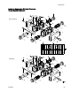
NOTE: If i
nstalling a one valve kit, it is not
necessar
y to disassemble the manifold stack as
shownint
he figure. Skip step 5 and go on to
step 6.
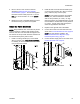
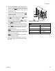
5. If your k
it is adding a manifold block (1), remove
the scre
ws (10). Slide the existing manifolds off
the rods
(15, 16), keeping the manifolds in the
correc
t order. Install the new manifold block (1).
The new
block must be in the bottom position to
mainta
in correct location of the solvent and dump
valves
. Screw the rods (16) included in the kit
into th
e existing rods. Slide the existing manifold
block
s onto the rods, being sure that they are in
the sa
me positions as before. Ensure all o-rings
(6, 17
) are in place, then install the screws (10).
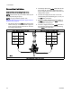
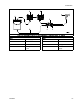
6. Install the valves as follows:
a. For a one valve kit, remove the plug
(4) and o-ring (2). Install a new o-ring
(2), the valve (3), and retainer (5),
using the valve installation tool. See
Replace a Color Valve, page 41.
b. For a manifold kit with one valve, install
the o-ring (2), valve (3), and retainer (5),
using the valve installation tool. See
Replace a Color Valve, page 41.Installthe
plug (4) in the unused manifold port.
c. For a manifold kit with two valves, install
the o-rings (2), valves (3), and retainers
(5), using the valve installation tool. See
Replace a Color Valve, page 41.
7. Install the o-ring(s) (12) and fluid fitting(s) (13).
Connect fluid lines to the fittings.
8. Install the air fitting(s) (14). Connect the tubing
from the solenoid valve(s) (see step 3) to the
fitting(s).
9. Install the control module cover.
10. Return the unit to service.
28 332455F