
User's Manual

Repair
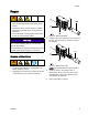
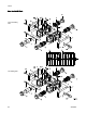
Replace a Sole
noid
1. Remove electrical power from the system.
2. Remove air supply pressure from the system.
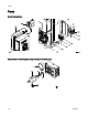
3. Remove the color change module cover (304).
4. Disconnect the two solenoid wires from
the color change board (302). See the
color change board wiring diagrams in the
Electrical Schematics, page 34.
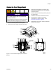
5. Remove the solenoid (310) from the manifold
(309).
6. Install the new solenoid.
7. Connect the two solenoid wires to the
color change board (302). See the color
change board wiring diagrams in the
Electrical Schematics, page 34.
8. Reinsta
ll the cover.
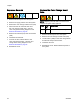
Replace the Co
lor Change Board
Fuse
NOTE: Replacing the fuse with a non-Graco fuse
voids the IS system safety approval.
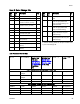
Fuse Part
No.
Description
F1 12369
0
Fuse; 125 mA, intrinsically safe
1. Remove ele
ctrical power from the system.
2. Remove the
color change module cover (304).
3. Locate fus
e F1 (302a) on the color change board.
Pull the f
use away from the board.
4. Install t
he new fuse.
5. Reinstal
l the cover. Restore electrical power to
the syste
m.
4
2
332455F