Kit Instructions ExactaBlend™ AGP Advanced Glazing Proportioner Heated Platen Kit 332511A EN For heating bulk supply of medium to high viscosity polysulfide and urethane materials. For professional use only. Not approved for use in explosive atmospheres or hazardous locations. 24R200 Heated platen kit, high volume Refer to ExactaBlend AGP Advanced Glazing Proportioner, Setup-Operation manual for maximum working pressure and model information.
Related Manuals Related Manuals Refer to ExactaBlend AGP Advanced Glazing Proportioner, Setup-Operation manual for the complete list of related manuals. Contents Related Manuals . . . . . . . . . . . . . . . . . . . . . . . . . . . 2 Contents . . . . . . . . . . . . . . . . . . . . . . . . . . . . . . . . . . 2 Warnings . . . . . . . . . . . . . . . . . . . . . . . . . . . . . . . . . 3 Overview . . . . . . . . . . . . . . . . . . . . . . . . . . . . . . . . . . 3 System Description . . . . . . . . . . .
Warnings Warnings The following warnings are for the setup, use, grounding, maintenance, and repair of this equipment. The exclamation point symbol alerts you to a general warning and the hazard symbols refer to procedure-specific risks. When these symbols appear in the body of this manual or on warning labels, refer back to these Warnings. Product-specific hazard symbols and warnings not covered in this section may appear throughout the body of this manual where applicable.
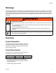
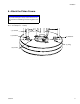
Component Identification Component Identification Heated Platen Kit C A B D F E H G FIG.
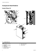
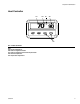
Component Identification Heat Controller AB AC 70 12 AA AD 90 AE FIG.
Installation Installation To avoid serious injury or machine damage, all electrical connections need to be done by a qualified electrician in compliance with local codes. Grounding Ground the system as instructed within this manual. The equipment must be grounded to reduce the risk of static sparking and electric shock. Electric or static sparking can cause fumes to ignite or explode. Improper grounding can cause electric shock. Grounding provides an escape wire for the electric current. 1.
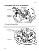
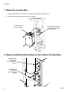
Installation 2. Install the Heat Coils and the Thermostat Switch. - (1) Thermostat - (2) Washers - (2) Screws - (6) 1/4-20 Studs - (6) Flat Washers - (6) Lock Washers - (6) Nuts 3. Connect the Ground Wires. Connect the ground wires to the terminal lug and to the platen covers (not shown in view). Attach the conduit to the platen cover and route the wires through the conduit when connections are complete.
Installation 4. Connect the Power Leads. Label “A” and “B” leads for identification in step 10. Route all the wires through the conduit when connections are complete. - (3) “A” Leads - (2) “B” Leads 5. Mount the RTD. Route the wire through the conduit when connections are complete.
Installation 6. Attach the Platen Covers. NOTICE To prevent damage to wires, ensure wires are not pinched when assembling and securing platen covers. NOTE: Torque the platen cover fasteners to 60 +/- 10 in-lbs (6.8 +/- 1.1 N•m).
Installation 7. Mount the Junction Box. a. Mount the junction box to the air motor located on the 55 gallon (208 liter) ram. b. Route the conduit to the junction box from the platen. - (2) #8-32 Screws - (2) Lock Washers - (1) 3/8-16 Bolt (Urethane) - (1) M8 Bolt (Polysulfide) - (1) Lock Washer 8. Mount the Heat Electrical Panel on the 5 Gallon (19 liter) Ram.
Installation 9. Route the Power Cord and Signal Cable to the Junction Box. Secure the power cord and signal cable to the base (A) cross bar. Routing 10.Connect the Leads in the Junction Box. Connect “A” leads, “B” leads, ground, and signal cable within the junction box. Replace the cover.
Installation 11.Connect the Power Cable from the Heat Electrical Enclosure to the Main Electrical Enclosure. 12.Connect Power to the Terminals and Ground.
Setup Setup 1. Turn the power on at the heated platen electrical enclosure. 2. Turn the power on at the heater power switch. 3. Set the desired platen temperature by pressing either the up or down arrow keys. NOTE: Temperature is displayed in Fahrenheit.
Operation Operation Startup Shutdown 1. Turn the power on at the heated platen electrical enclosure. 1. Turn the power off at the heater power switch. 2. Turn the power on at the heater power switch. NOTE: If the entire machine is to be disconnected from electrical power, turn the power off at the heated platen electrical enclosure. 3. Set the desired temperature. Refer to page 5 for details.
Maintenance Maintenance Platen Maintenance Remove and Reinstall Platen Wipers Refer to Supply Units Repair-Parts manual for instructions. F If the platen does not come out of the pail easily when the pump is being raised, the air assist tube or check valve may be plugged. A plugged valve prevents air from reaching the underside of the plate to assist in raising it from the pail. 1. Turn off main disconnect at the machine. 2. Allow equipment to cool. C Bleed Stick B H 3.
Troubleshooting Troubleshooting Before performing any troubleshooting procedure: 1. Perform Pressure Relief Procedure In the ExactaBlend AGP Advanced Glazing Proportioner, Setup-Operation manual. 2. Turn off main disconnect at the machine. 3. Allow equipment to cool. Try the recommended solutions in the order given for each problem, to avoid unnecessary repairs. Also, determine that all circuit breakers, switches, and controls are properly set and wiring is correct before assuming there is a problem.
Troubleshooting Problem No heat. Cause Verification Solution Tripped circuit breaker. Visually check circuit Determine cause of tripped breaker for a tripped condi- circuit breaker. Then repair tion. fault and reset main circuit breaker. Low power. Measure voltage across cir- 1. If voltage is lower than expected, use electrical cuit breakers. Voltage schematic to locate should measure between faulty wiring or connec190 and 264 Vac. tion. 2. Have a qualified electrician service electrical components.
Repair Repair Replace Platen Heaters and Sensor c. Disconnect four platen heater wires (labeled A and B) and RTD sensor (R) connector in the terminal box. d. Remove screws and washers. Remove platen heater blocks (B) and RTD sensor (R). 55 Gallon Platen Heater and Sensor 6. Install new platen heaters and RTD sensor (R). Secure RTD sensor (R) with screw and washer. Secure platen heater blocks with nuts and washers. 1. Turn off main disconnect at the machine. 2. Allow equipment to cool. 7.
100 101 102 103 104 105 106 107 108 109 110 111 112 113 114 115 116 117 118 119 120 121 122 123 124 125 126 127 128 129 130 131 132 133 134 135 136 137 138 139 140 141 142 143 144 145 146 147 148 149 1 1L1 1L1 L1 1L1 GND HARNESS 16U358 HARNESS 16U358 CB CB 20A 1120 1100 HARNESS 16U345 CB 5A CB HARNESS 16U353 1 1380 1360 CRM C1 OX ON HARNESS 16U354 T1 T3 T2 CON120 L3 L2 L1 HARNESS 16U354 SW-1 POWER C2 OFF 1180 HARNESS 16U345 LABEL WITH WIRE NUMBERS MARKED AS SHOWN SEE X
Parts Parts Heated Platen Kit, 24R200 2 2 6 5, 26 3 5 11 22 23 28 11 14 7 14 FIG.
Parts 32 30 19 33 34 16, 45 25 36 35 4 21 18 27 17 8 24 8 10 39 1 3 44 43 40 42 37 44 38 43 41 40 FIG.
Parts Ref 1 2 3 4 5 6 7 8 9 10 11 12 13 14 15 16 17 18 19 20 21 22 23 24 25 26 ▲ 27 28 29 30 32 33 34 35 36 22 Part --------------16D383 ----------15V427 ------------------261821 --15J075 --------------15B137 --- Description FERRULE, wire, 14awg FASTENER, platen, cover COUPLER, conduit ENCLOSURE, platen, heated COVER, platen front, assembly PLUG, finishing, 13/16, nickel plate STUD, 1/4-20 x 1.
Parts Ref 37 38 39 40 41 42 43 44 45 Part ----24R870 ------------- Description BRACKET, mount, top BRACKET, mounting, ram MODULE, heat WASHER, M6 SCREW, socket head, M6x25mm SCREW, socket head, M6x16mm WASHER, lock, M6 NUT, hex, M6 SCREW, cap, M8x20mm Quantity 2 2 1 16 8 8 16 16 1 ▲ Replacement Danger and Warning labels, tags and cards are available at no cost. --- Not available for individual sale.
Parts Heat Enclosure, 24R870 107 108 110 128 109 109 101, 112, 113 111 116 127 132 136 106 134 108 109 FIG.
Parts 118 117 114, 115 130 130 130 139 131 102, 103 119 124 121 126 102, 104 122 125 129 122 123 118 120 FIG.
Parts Ref Part 101 --102 --103 --104 --106 --107 121148 108 --109 --110 126999 111 24R941 112 127106 113 127107 114 --115 --116 --117 --118 --119 --120 --121 --122 --123 --124 --125 --126 --127 --128 --129 --130 --131 --132 --134 --136 ▲ 196548 139 121599 Description NUT, machine hex, M4-0.7 NUT, hex, M5-0.8 WASHER, lock, external, M5 WASHER, plain, #10 RETAINER, cord HANDLE, disconnect, electrical GRIP, cord SCREW, M5-0.
Parts 332511A 27
Graco Standard Warranty Graco warrants all equipment referenced in this document which is manufactured by Graco and bearing its name to be free from defects in material and workmanship on the date of sale to the original purchaser for use. With the exception of any special, extended, or limited warranty published by Graco, Graco will, for a period of twelve months from the date of sale, repair or replace any part of the equipment determined by Graco to be defective.