Instructions Dyna-Star® HP Vent Valve Kit 332519F EN Used with the Dyna-Star HP or HF Pump to reduce system pressure and allow injector to reset. For professional use only. Part No.: 77X540 Maximum Working Pressure: 3500 psi (241 bar, 24 MPa) Important Safety Instructions Read all warnings and instructions in this manual and the Dyna-Star HP and HF Pump instruction manual included with your unit. Save all instructions.
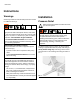
Instructions Instructions Warnings Installation See the Dyna-Star HF and HP Pump Instruction manual for additional warnings. Pressure Relief Follow the Pressure Relief Procedure whenever you see this symbol. SKIN INJECTION HAZARD High-pressure fluid from dispense device, hose leaks, or ruptured components will pierce skin. This may look like just a cut, but it is a serious injury that can result in amputation. Get immediate surgical treatment.
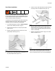
Instructions Vent Valve Installation 5. Loosen, remove and discard the 3 socket head cap screws (b) from the adapter block (a) (FIG. 3). a Reference numbers used in these instructions correspond to Parts included in Kit and are provided on page 5. Parts identified with an alpha character are user provided or already installed components. b c To ensure the correct pressure relief valve is used and pressure settings are correct, always use new parts included in your Vent Valve Kit for reassembly. 1.
Instructions 8. Install vent valve (1) to pump surface using the 3 cap screws (4) included in the kit (FIG. 5). Hold the vent valve tight to the surface of the pump to ensure o-rings stay in place during installation.Torque screws to 17-19 ft-lbs (23-26 N.m). 11. Connect cable (d) to valve cartridge (c) (FIG. 7). d c 1 4 FIG. 7 12. Install other end of cable (d) to solenoid control device. FIG. 5 NOTE: 9. Install lubrication line to vent valve pump outlet port marked “0” (FIG. 6).
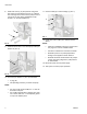
Parts Parts Ref 1 2 3 4 8 9 10 Description MANIFOLD, electric vent valve VALVE, cartridge, 24VDC VALVE, pressure relief, 3500 psi SCREW, cap, socket, M8 x 1.25 O-RING PLUG, pipe, 1/8 in. npt PLUG, 1/4 in. npt 2 Qty 1 1 1 3 2 1 1 9 8 Accessories 1 Part No. Description 24N402 CABLE, 6 ft, vent valve, 2 pin for vent valve control 77X529 CABLE, power injector system only. Use with 77X528 77X528 CABLE, power extension, 15 ft (4.6m), use with 77X529 10 3 4 Technical Data .
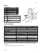
Dimensions 4.95 in. (12.57 cm) 1.5 in (3.81 cm) 2.5 in. (6.36 cm) 1.5 in. (3.81 cm) 4.0 in. (10.16 cm) Graco Information For the latest information about Graco products, visit www.graco.com. TO PLACE AN ORDER, contact your Graco distributor or call to identify the nearest distributor. Phone: 612-623-6928 or Toll Free: 1-800-533-9655, Fax: 612-378-3590 All written and visual data contained in this document reflects the latest product information available at the time of publication.