Operation - Repair RS™ Gun Cutter Assemblies 332574D EN For use with the RS Guns. For professional use only. Important Safety Instructions Read all warnings and instructions in this manual and the RS Gun and Cutter, Operation-Repair manual. Save all instructions.
Contents Related Manuals . . . . . . . . . . . . . . . . . . . . . . . . . . . 3 Component Identification . . . . . . . . . . . . . . . . . . . . 4 Cutter, 24E512, External Mix Gun, Series C and Prior Cutter, 24P681, Internal Mix Gun, Series A . 4 Cutter, 24E512, External Mix Gun, Series D Cutter, 24P681, Internal Mix Gun, Series B . 5 Setup . . . . . . . . . . . . . . . . . . . . . . . . . . . . . . . . . . . . . 6 Operation . . . . . . . . . . . . . . . . . . . . . . . . . . . . . . . . .
Related Manuals Related Manuals The following is a list of component manuals written in English. These manuals and any translated versions available can be found at www.graco.com.
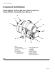
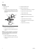
Component Identification Component Identification Cutter, 24E512, External Mix Gun, Series C and Prior Cutter, 24P681, Internal Mix Gun, Series A AH AK AC AG AD AA AF AB ti21012a AN AE AJ Key: AA AB AC AD AE AF Blade Cartridge Cutter Head Assembly Cap Anvil Anvil Cap Glass Feed Anvil to Blade Tension Adjustment Knob AG Anvil to Blade Tension Lockdown AH Air Motor AJ Idler Wheel AK Motor Lock button AL Cover (not shown) AM Chute (not shown) AN Idler Lock Down Screw FIG.
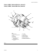
Component Identification Cutter, 24E512, External Mix Gun, Series D Cutter, 24P681, Internal Mix Gun, Series B AH AK AC AG AD AP AA AF AB AN AE AJ Key: AA AB AC AD AE AF Cutter Head Cutter Head Clamp Screw Anvil Anvil Cap Glass Feed Anvil to Blade Tension Adjustment Knob AG Anvil to Blade Tension Lockdown AH AJ AK AL AM AN AP Air Motor Idler Wheel Motor Lock button Cover (not shown) Chute (not shown) Idler Lock Down Screw Air Motor Lock Down Screw FIG.
Setup Setup 1. Engage trigger lock. 3. Insert glass strands into feed. 2. Install cutter: 4. Adjust anvil to blade tension: a. If necessary, use a crescent wrench to adjust pivot (541) so that it is parallel to gun front end and the open end points to the front of the gun. See FIG. 3. 541 542 630 a. Release lockdown (AG). See FIG. 1 on page 4. b. Adjust tension knob (AF) as desired. c. Tighten lockdown (AG). d. Release idler lock down screw (AN). e.
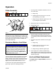
Operation Operation Cutter Assembly 1. Do a bag check to establish a baseline for the current cutter output. a. Weigh a bag. AH AC b. Dispense glass into the bag for 15 or 30 seconds depending on the output. c. Weigh the bag to determine glass output. This is your fiberglass output baseline. 2. Add another strand of roving to the cutter inlet. 3. Engage trigger lock. AG AF AJ To prevent skin injection, engage the trigger lock before adjusting cutter motor. FIG.
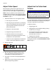
Operation Adjust Cutter Speed When dispensing a material and glass mixture, the speed at which the cutter spins can be adjusted to ensure the correct ratio of glass to dispensed material. NOTE: It may be possible to prevent premature anvil and blade wear by slowing the cutter speed and adding an additional strand of roving. See Premature Blade or Anvil Wear on page 7. Adjust Anvil to Cutter Head Tension NOTICE More tension leads to the anvil and blades wearing out faster.
Operation Adjust Anvil to Idler Tension Adjust Cutter Air Pressure To adjust the anvil (AC) to idler (AJ) tension, the idler position can be adjusted. See FIG. 4 on page 7. Adjust the incoming air pressure according to the table below. 1. Follow Pressure Relief Procedure found within the RS Gun and Cutter, Operation-Repair manual. 2. Engage trigger lock. 3. Remove cover (627). See page 20. Number of Strands US Metric One Strand Two Strands Three Strands 50-75 psi 80-125 psi 80-125 psi 3.
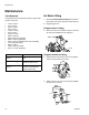
Maintenance Maintenance Air Motor Oiling Tools Required The following tools are required to perform regular maintenance on the gun. • • • • • • • • • • • • • • • 7/16 in. wrench 1/2 in. wrench 9/16 in. wrench 5/8 in. wrench 11/16 in. wrench 3/4 in. wrench 13/16 in. wrench 5/64 in. allen key 3/32 in. allen key (supplied) 9/64 in. allen key (supplied) 3/16 in. allen key (supplied with cutter assembly) 1/2 in. deep well socket 9/32 in. socket 7/32 in. deep well socket 5/16 in. nut drive (supplied) 1.
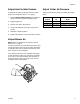
Maintenance Replace Anvil 7. Remove anvil (AC). 8. Install new anvil onto sleeve. 9. Install anvil cap. 10. Install cover and knob. AH AK AC AG AD AA AP NOTICE More tension between the anvil and blades leads to the anvil and blades wearing out faster. To prevent premature wear and to maximize anvil and blade life, use the minimum tension required to cut the glass and make small increases in tension when strands are not cut correctly. 11. Adjust Anvil to Cutter Head Tension, page 8.
Maintenance Replace Blades 10. Adjust Anvil to Cutter Head Tension, page 8. If glass is not getting cut properly, verify the tension is correct before replacing the blades. 1. Follow Pressure Relief Procedure found within the RS Gun and Cutter, Operation-Repair manual. 2. Engage trigger lock. 3. Remove cover (627). See page 20. FIG. 6 Blades are sharp. Always wear protective gloves to prevent cuts when the cutter cover is removed. 4.
Maintenance Replace Chopper Chute Liner Replace Muffler Filters (Kit 24H280) 1. Follow Pressure Relief Procedure found within the RS Gun and Cutter, Operation-Repair manual. 1. Follow Pressure Relief Procedure found within the RS Gun and Cutter, Operation-Repair manual. 2. Engage trigger lock. 2. Engage trigger lock. 3. Remove the four screws holding the muffler cap on to the air motor. 3. Remove the cover. 4. Discard the old mufflers and replace. 4. Remove the cutter cover plate. 5.
Troubleshooting Troubleshooting Problem Cause Premature anvil or blade wear Excessive tension between anvil and cutter Adjust Anvil to Cutter Head Tension, page 8 head Roving binds up in Cutter Solution Cutter speed faster than necessary Premature Blade or Anvil Wear, page 7 Obstruction in roving path Ensure the roving path is free from obstruction Overspray/binder build up on internal com- Clean components and reinstall the cover ponents Resin on roving Clean as necessary, keep roving away from
Repair Repair Air Motor Component Removal 6. Pull upwards to remove the muffler housing. Refer to FIG. 10 for the following steps. 1. Loosen the set screws and pull gently to remove the cutter head assembly. 2. Remove the four screws that secure the air motor to the plate. 3. Separate the air motor from the plate. r_258899_3a0232_1a r_258900_3a0232_1k FIG. 11 7. Use an arbor press to remove the nut bearing cap from the muffler housing. FIG. 10 Refer to FIG. 11 for the following steps. 4.
Repair Air Motor Component Installation 3. Screw the air motor assembly on the nut bearing cap. Torque to 120-140 in-lb (14-16 N•m). 1. Lubricate o-rings and install the air motor into the muffler housing. NOTICE To avoid damage to the o-rings caused by the threads of the air motor, insert the air motor as shown below. r_258899_3a0232_5k 4. Use an arbor press to push the muffler housing down until it is flush with the bearing cap. Correct r_258899_3a0232_6k 2.
Repair Air Motor Replacement 1. Verify o-ring (603) is installed between the back plate (601) and the air motor (602). NOTICE The air motor will not function properly if the air motor is installed incorrectly. In the following step, ensure the air motor is installed as described. 2. With the air motor and back plate oriented as shown below, use four screws (604) to secure them together. Two air holes align with the “X” as shown.
Parts Parts Cutter Assembly, 24E512-External Mix, 24P681-Internal Mix with Cutter Heads NOTICE To prevent undesired operation, do not disassemble any part of the air motor (602) except for the air motor muffler as shown below. 106 6 153 130 104 6 1 103 129 114 113 154 102 123 111 2 112 152 132 144 2 131 122 147 2 142 121 101 134 126 143 2 116 146 125 147 117 2 119 112 2 124 115 117 2 120 118 127 136 128 145 7 155 1 Apply a light amount of lubricant to o-rings.
Parts Ref 100 101 102 103 104 106 111 112 113 114 115 116❄ 117❄★ 118 119❄ 120★ 121 122 123 124 125◆‡ 126 127◆‡ 128◆‡ 129 130 131◆‡ 132 134 136◆‡ 142 143◆‡ 144◆‡ 145◆‡ 332574D Part 199359 16C677 24E511 117519 111945 Description Qty DOCUMENT, declaration 1 PLATE, cutter back 1 MOTOR, air 1 O-RING 1 SCREW, cap, flat head 4 SCREW, set, #8-32x1/2 long, 124612 2 SST 16C686 PLATE, spring retainer 1 SCREW, cap, socket head, 123909 2 8-32x.
Parts Cutter Assembly, 24E512-External Mix, 24P681-Internal Mix with Blade Cartridges NOTE: Series A cutter assemblies are no longer available for purchase and are shown for reference only and spare parts ordering. NOTICE To prevent undesired operation, do not disassemble any part of the air motor (602) except for the air motor muffler as shown below.
Parts Ref 600 601 602 603 604 605✿ 606✿ 607✿ 608✿ 609 Part 199359 16C677 24E511 117519 111945 16C995 124612 16C996 123910 24E448 24F602 24E449 610✿ 258905 611 16C686 612 123909 613 123882 614 16C678 615 16C679 616❄ 258902 617❄★ 124588 618 123672 619❄ 262711 620★ 258901 621 16C687 622 124048 623 16C691 624 123883 625◆‡ 124316 626 24F038 24M569 627◆‡ 24N712 628◆‡ 16C697 629 16C676 630 124057 631◆‡ 16D534 632 110755 633 16E024 634 24E432 332574D Description Qty DOCUMENT, declaration 1 PLATE, cutter back 1
Parts Air Motor, 24E511 NOTICE To prevent undesired operation, do not disassemble any part of the air motor that is not available for individual sale. See related parts table. 1206 2 4 1207 1216 2 1209 1217 1215 1214 1208 1 1210 1213 1211 1 1212 1 1 Apply a light amount of lubricant 118665 to o-rings. 2 Apply thread locker to threads. 4 Torque to 120-140 in-lb.
Parts Ref 1206 1207 1208 1209 1210 1211 1212 1213❄ 1214✿ 1215 1216 1217 Part 16C443 16C438 116768 16C436 16C434 113082 117519 111603 124420 16D323 127263 123742 Description NUT, bearing retaining PLUNGER, quick release PACKING, o-ring SPACER, spring HOUSING, speed control PACKING, o-ring O-RING PACKING, o-ring, ptfe MUFFLER, air motor CAP, muffler, air motor SCREW, cap, socket head, 8-32 SPRING, compression Qty 1 1 1 1 1 1 1 1 3 1 4 1 ✿ Parts included in muffler felt kit 24H280.
Accessories Accessories Chopper Air Shutoff, 24F706 Oil for Air Motor 1102 1101 1103 Ref 1101 1102 1103 Part 15B565 123737 16F710 24F706_3A0232_1a 202659, 16 oz. Description VALVE, ball FITTING, tube, push connector CONNECTOR, 3/8 tube MSDS sheets available at www.graco.com. Cutter Chop Chutes Additional chopper chutes for adapting to different glass pattern needs.
Accessories Cover and Chutes Tools Hex Keys for Guns, 24F007 24H282 Shown Includes: • One 3/32 in. hex key • One 9/64 in. hex key Hex Keys for Cutter, 24F008 ti21024a 24P683 Shown Includes: • One 3/32 in. hex key • One 9/64 in. hex key • One 3/16 in. hex key Carbide Resin Seat, 24M833 Ideal for use with heavily filled materials. It is to replace standard resin seat 16C104.
Accessories Cutter Head Kits Blades, 24R606 Pack of 100 blades.
Technical Data Technical Data RS Cutter Assemblies US Metric Air Inlet Working Pressure 24E512 80-125 psi 5.5-8.6 bar, 0.55-0.86 MPa 24P681 Minimum Air Flow (at 100 psi, 7 bar, 0.7 Mpa) 24E512 16.5 scfm 0.47 m3 per min. 24P681 Cutter Maximum Glass Output At 100 psi (7 bar, 0.7 MPa) static air pressure@ the machine and 75 ft hose bundle One Strand 3.1 lb/min 1.4 kg/min Two Strands 5.9 lb/min 2.7 kg/min Three Strands 7.0 lb/min 3.2 kg/min Cutter Maximum Glass Output At 100 psi (7 bar, 0.
Graco Standard Warranty Graco warrants all equipment referenced in this document which is manufactured by Graco and bearing its name to be free from defects in material and workmanship on the date of sale to the original purchaser for use. With the exception of any special, extended, or limited warranty published by Graco, Graco will, for a period of twelve months from the date of sale, repair or replace any part of the equipment determined by Graco to be defective.