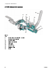
Instructions - Parts M680 Mortar Sprayer 332612A EN High performance, high output spray packages for high viscosity materials, such as mortars, mastics, and epoxies. For professional use only. Important Safety Instructions Read all warnings and instructions in all manuals. Save all instructions. 1000 psi (7 MPa, 69 bar) Maximum Fluid Working Pressure 150 psi (1.0 MPa, 10 bar) Maximum Air Inlet Pressure 100 psi (0.
Contents Related Manuals ................................................ 2 Warnings ........................................................... 3 Models............................................................... 6 Component Identification..................................... 7 Overview..................................................... 7 Details......................................................... 8 Mortar Spray Applicator................................ 9 HTX 680 (Internal Air) Applicator........
Warnings Warnings The following warnings are for the setup, use, grounding, maintenance, and repair of this equipment. The exclamation point symbol alerts you to a general warning and the hazard symbols refer to procedure-specific risks. When these symbols appear in the body of this manual or on warning labels, refer back to these Warnings. Product-specific hazard symbols and warnings not covered in this section may appear throughout the body of this manual where applicable.
Warnings WARNING EQUIPMENT MISUSE HAZARD Misuse can cause death or serious injury. • Do not operate the unit when fatigued or under the influence of drugs or alcohol. • Do not exceed the maximum working pressure or temperature rating of the lowest rated system component. See in all equipment manuals. • Use fluids and solvents that are compatible with equipment wetted parts. See Technical Data in all equipment manuals. Read fluid and solvent manufacturer’s warnings.
Warnings WARNING PERSONAL PROTECTIVE EQUIPMENT Wear appropriate protective equipment when in the work area to help prevent serious injury, including eye injury, hearing loss, inhalation of toxic fumes, and burns. This protective equipment includes but is not limited to: • Protective eyewear, and hearing protection. • Respirators, protective clothing, and gloves as recommended by the fluid and solvent manufacturer. SUCTION HAZARD Powerful suction could cause serious injury.
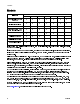
Models Models Includes Model 9: Pump installed on Cart 24T837 1 Basic Spare Parts Kit 2 (included in tool box) Feed Hopper 24T853 3 Standard 35 ft (1.7 m) Hose Bundle 24T852 4 Flex Applicator 24T947 5 HTX 680 Manifold Applicator 24U209 6 Additional Spare Parts 7 Additional 25 ft (7.
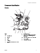
Component Identification Component Identification Overview AD AJ AB AF AA AK AC Figure 1 AE AK Key: AA AB AC AD AE AF 332612A Material Hopper Air Motor Lower Cart Applicator Material Hose (connects pump to whip hose) AI AH AG AH AI AJ AK AG ti21568a Material Whip Hose Air Supply to Applicator (for Air Assist and Air Motor ON/OFF Pilot Valve), shown disconnected Return Air to Air Motor ON/OFF Pilot Valve System Air Inlet Optional hose extension 7
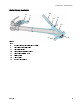
Component Identification Details X H E D B L Y A K F S N C U J T S M P K G R W U T M G U T M W V Detailed View Figure 2 M N Key: A Air Inlet, 3/4 npt(f) Claw (Chicago) Fittings B C D E F Bleed Type Master Air Valve (required) Air Pressure Relief Valve Air Filter (40 micron) Motor Air Pressure Gauge Motor Air Pressure Regulator Adjustment Knob Pilot Ball Valve (starts/stops Air Motor) Motor Air Pilot Valve Zero Cavity Relief Valve Air Assist Tube Grounding Wire, required (see Grou
Component Identification Mortar Spray Applicator M U CA CB CC CD CF CE Figure 3 Key: M U CA CB CC CD CE CF 332612A Needle Valve for Air Assist Flow Control Air Assist Shutoff Ball Valve Air Assist Air Line Air Needle (adjustable position) Air Needle Retaining Screw Fluid Housing Tip (Nozzle) Rubber Tip Retainer 9
Component Identification HTX 680 (Internal Air) Applicator DG M DA DE U DB DD DC DF Figure 4 Key: M U DA DB DC DD DE DF DG 10 Needle Valve for Air Assist Flow Control Air Assist Shutoff Ball Valve Air Assist Air Line Fluid and Air Manifold Tip (Nozzle) Tip Retainer Air Check Valve Fluid Inlet Swivel Handle 332612A
Component Identification System Components * Required system components. Air Regulator Adjustment (F) Adjusts air pressure to the motor and fluid outlet pressure of pump. Read air pressure on gauge (E). To avoid tipping over, ensure cart is on a flat and level surface. Failure to do so could result in injury or equipment damage. * Bleed Type Master Air Valve (B) • Be sure the valve is easily accessible from the applicator.
Grounding Grounding The equipment must be grounded to reduce the risk of static sparking and electric shock. Electric or static sparking can cause fumes to ignite or explode. Improper grounding can cause electric shock. Grounding provides an escape wire for the electric current. 2. Connect the other end of the ground wire to a true earth ground. 3. Ground the object being sprayed, fluid supply container, and all other equipment in the work area. Follow your local code.
Setup Setup 9. Wrap blue, velcro, camlock retaining straps around each camlock connection to secure. Tools Required • Two adjustable wrenches • Non-sparking hammer or plastic mallet 1. Ground sprayer. See Grounding, page 12. 2. Check Throat Seal Liquid (TSL) level in packing nut (R). Fill 1/2 full with TSL. R This includes the two camlocks between the hopper and pump lower, the camlock at the pump outlet, the camlocks on the fluid hoses, and the camlock on the applicator inlet.
Pressure Relief Procedure Pressure Relief Procedure Follow the Pressure Relief Procedure whenever you see this symbol. This equipment stays pressurized until pressure is manually relieved. To help prevent serious injury from pressurized fluid, such as skin injection, splashing fluid and moving parts, follow the Pressure Relief Procedure when you stop spraying and before cleaning, checking, or servicing the equipment. 1. Flush the system. See Flush, page 26. 2. Close incoming air ball valve (B).
Wet Out the System Wet Out the System NOTICE To prevent material curing in system, never load mortar or epoxy into a dry system. Loading mortar or epoxy into a dry system will cause the material to stick to internal components and cure causing damage and requiring replacement of those parts. Always wet out the system by circulating clean fluid through the applicator back into the hopper before loading any mixed mortar.
Wet Out the System 8. Open the motor on/off pilot ball valve (G) located on base of applicator. 10. Rotate the air regulator adjustment knob (F) clockwise until pump begins to move slowly. F Figure 14 9. Open bleed type master air valve (B). ti21578a ti21570a Figure 16 NOTICE To prevent damage to pump seals caused by cavitation, run the pump slowly until the system is primed. 11. Continue running the pump until all of the flushing fluid is dispensed into the pail. The system is now wetted out.
Wet Out the System 12. To stop dispensing, close the air motor on/off pilot ball valve (G) and the main bleed type master air valve (B). B A ti21575a Figure 18 332612A 13. If needed, drain remaining fluid from system. Materials that separate more easily may require draining the remaining fluid from the system. Check material data sheet to determine whether it is necessary to drain the remaining fluid from the system. a. Place grounded metal drain pan beneath pump lower inlet fittings. b.
Mix the Material Mix the Material Always wet out the pump, hose, and applicator before loading the mortar or epoxy material. See Wet Out the System, page 15. Always follow the material manufacturer’s instructions for the material being sprayed. Mortar must be thoroughly mixed to a smooth consistency before loading it in the hopper. • Always add the powder slowly to the fluid while mixing. Do not add fluid to the powder.
Prime with Mortar or Epoxy Prime with Mortar or Epoxy NOTICE To prevent material curing in system, never load mortar into a dry system. Loading mortar into a dry system will cause the mortar to stick to internal components and cure causing damage and requiring replacement of those parts. The applicator nozzle or tip must be removed during priming. Always push out any remaining “wet out” fluid into a waste container before circulating mortar.
Prime with Mortar or Epoxy 12. Continue running the pump until a steady stream of material comes from the applicator. 10. Open bleed type master air valve (B). B ti21632a Figure 23 13. To stop dispensing, close the motor ON/OFF pilot ball valve (G). Do not close the fluid ball valve (V) when the air motor is running. ti21574a Figure 21 NOTICE To prevent damage to pump seals caused by cavitation, run the pump slowly until the system is primed. 11.
Spray Spray NOTICE Do not operate the pump motor with the applicator material ball valve (V) closed. This may cause the pump or hose to pack out. Prevent Packout To avoid “packing out” the pump or hose: • Use the lowest pressure and largest nozzle size that provides an acceptable spray pattern. This will also result in seals and wear parts lasting much longer. • Do not use any more fluid hose than is necessary. • Use an applicator with a rubber tip retainer that will blow off if it plugs.
Spray 5. Install tip on applicator by stretching rubber retainer with a screwdriver or screwing on retainer, depending on your application kit. 9. Adjust air motor regulator adjustment knob (F) until desired material flow rate is achieved. Turn clockwise to increase pressure, counterclockwise to decrease pressure. E F Figure 26 6. Open air assist valve (U) and adjust the air assist needle valve (M). See Details, page 8 . 7. Open the material ball valve (V) on the base of the applicator.
Spray Adjustments (Mortar Spray Applicator) Spray Adjustments (Mortar Spray Applicator) M CA U CB CC CD CF CE Figure 28 Key: M U CA CB CC CD CE CF Needle Valve for Air Assist Flow Control Air Assist Shutoff Ball Valve Air Assist Air Line Air Needle (adjustable position) Air Needle Retaining Screw Fluid Housing Tip (Nozzle) Rubber Tip Retainer General Adjustments The spray pattern can be adjusted by changing: • Tip (CE) size • Fluid flow, use air motor regulator adjustment knob (G) • Air flow, use
Spray Adjustments (Mortar Spray Applicator) Withdrawing needle too far can force air pressure back into fluid hose, slowing material flow. NOTE: 2. Insert screwdriver through hole in tab of nozzle retaining cap. 3. Push screwdriver head against notch on applicator tip and pry nozzle retaining cap over lip until it snaps into place. Spray Techniques 1. Test the spray pattern on cardboard. Hold the applicator 6-18 in. (150-450 mm) from the surface. Use this spraying distance for most applications. 2.
Spray Adjustments (HTX 680 Applicator) Spray Adjustments (HTX 680 Applicator) DG M DA DE U DB DD DC DF Figure 30 Key: M U DA DB DC DD DE DF DG Needle Valve for Air Assist Flow Control Air Assist Shutoff Ball Valve Air Assist Air Line Fluid and Air Manifold Tip (Nozzle) Tip Retainer Air Check Valve Fluid Inlet Swivel Handle The spray pattern can be adjusted by changing: • Tip (DC) size • Fluid flow, use air motor regulator adjustment knob (G) • Air flow, use needle valve (M) The standard applicator a
Flush Flush 2. Remove applicator tip and retainer. NOTICE Failure to flush prior to material curing in the system will result in damage to system and may require replacement of all system parts in contact with the material. NOTICE If the zero cavity pressure relief valve has been used to relieve pressure, the valve must be flushed to prevent material hardening in zero cavity relief valve. If that is not sufficient, remove, disassemble, and clean the valve then reinstall.
Flush 6. Open bleed type master air valve (B) to begin dispensing. 10. Place applicator in the system hopper with the outlet pointing down to enable fluid circulation. If flushing with solvent, do not submerge the applicator in the solvent. 11. Circulate clean water or solvent: a. Fill the system hopper with clean water or solvent. NOTE: B ti21574a Figure 34 7. When the material level in the hopper is within a few inches of the material inlet at the bottom: a.
Flush fluid ball valve is open before opening pilot ball valve (G). When the fluid ball valve gets hard to operate, it should be disassembled, cleaned, and re-packed with grease. Decrease air pressure to air motor back to operating pressure. Close the air motor pilot ball valve (G). Place applicator outlet in a grounded metal waste container. Open air motor pilot ball valve (G) to dispense into grounded metal waste container.
Notes Notes 332612A 29
Disassemble and Clean the Pump (Daily) Disassemble and Clean the Pump (Daily) Suggested Tools • 5/8 in. box end wrench or 5/8 in.
Disassemble and Clean the Pump (Daily) Key BA BB BC BD BE BF BG BH BI BJ BK BL BM BN BP BR BS BT BU BV Inlet Elbow with Camlock Inlet Housing Clamp Inlet Housing Assembly Inlet Ball Inlet Ball Stop Pump Rod Assembly Outlet Ball Stop Piston Seal Cylinder Cylinder Clamp Outlet Housing Throat Packing Packing Nut (non-adjustable) Hopper Pump Outlet Hopper Release Camlock Outlet Ball Cylinder O-rings Outlet Housing Lock Nut Ball Cage Spring As items are disassembled, use a soft brush and water or a compatible
Disassemble and Clean the Pump (Daily) 9. Slide cylinder (BI) over rod (BF) with o-ring (BT) installed between outlet housing (BK) and cylinder (BI). BF3 If the o-ring (BT) does not stay in place while assembling the cylinder (BI) to the housing (BK), the cart may need to be tipped upright to install properly. ti21656a After clamp is installed, tip cart back to Figure 39 horizontal position to finish assembly. 11. Pull rod (BF) down and out of outlet housing (BK). 10.
Shutdown 17. Wrap blue, velcro, camlock retaining straps around each camlock connection to secure. This includes the two camlocks between the hopper and pump lower, the camlock at the pump outlet, the camlocks on the fluid hoses, and the camlock on the applicator inlet. The retaining straps should be tight and must not be able to slide off camlock. 18. Add TSL to the packing nut (BM) until 1/2 full. NOTE: Shutdown NOTICE To prevent rust, never leave water or water-based fluid in pump overnight. 1.
Maintenance Maintenance Preventative Maintenance The operating conditions of your particular system determine how often maintenance is required. Establish a preventive maintenance schedule by recording when and what kind of maintenance is needed, and then determine a regular schedule for checking your system. Daily Maintenance 4. 5. 1. Flush the system. See Flush, page 26. 2. Relieve pressure. See Pressure Relief Procedure, page 14. 3.
Troubleshooting Troubleshooting • Output low on both strokes. – To prevent skin injection and splashing, never open a camlock hose or applicator fitting while there is pressure in the fluid line. See Pressure Relief Procedure, page 14. 1. Perform Pressure Relief Procedure. See Pressure Relief Procedure, page 14. 2. Check all possible problems, causes, and solutions listed below before disassembling pump. PROBLEM — CAUSE — SOLUTION Example: • – Cause. ♦ Solution. Problem. • Does not operate.
Troubleshooting • Poor finish or irregular spray pattern. – – – • ♦ See applicator manual; read fluid manufacturer’s recommendations. – Inadequate air assist air pressure. ♦ Adjust air assist needle valve. Cannot open or close air motor pilot ball valve on Dirty air clogged the air motor pilot valve. ♦ If no ball valve is immediately available: Bypass the air motor pilot valve so air is always supplied to air motor, regardless of applicator pilot valve position.
Repair Repair To prevent skin injection and splashing, never open a camlock hose or applicator fitting while there is pressure in the fluid line. Perform Pressure Relief Procedure, page 14, before performing any repair procedure. Replace Pump Components To replace any pump components (excluding the air motor), perform the Disassemble and Clean the Pump (Daily), page 30, procedure. Replace Air Motor 1. Perform Pressure Relief Procedure, page 14. 2.
Parts Parts M680 Systems 7 4 67 3 1 49 66 68 4 8 65 47 41 45 48 6 7 50 7 18 3 2 46 42 5 4 26 20 6 7 51 53 17 1 44 5 1 15 1 14 7 20 10 13 43 3 11,55,58 12,55,58 Assemble fitting (15) and zero cavity relief 1 ti22048a Pack grease around the end of the 4 valve (17) then assemble to swivel (14) zero-cavity relief valve in front of the with relief hole pointing downward or at the threads. pump. 2 3 Apply pipe sealant to all non-swiveling pipe threads.
Parts Quantity Ref Part Description 6 104572 WASHER, lock spring 7■ 114193 SCREW, machine, hex washer 24T834 24T835 24T836 24T837 262909 262926 262927 4 4 4 4 4 4 4 12 10 12 10 12 10 12 1 1 1 1 1 1 head 8 155470 SWIVEL, union, 90 degree 1 10■ - - - BRACKET, hopper 1 1 1 1 11■ 16V510 CAM AND GROOVE, elbow, 1 1 1 1 1 1 1 1 1 1 1 2 inch 12■ 16V509 CAM AND GROOVE, 2 inch x 1-1/2 npt 13■ 16U536 HOPPER 1 14 160022 UNION, adapter 1 1 1 1 1
Parts Quantity Ref Part Description 24T834 24T835 24T836 24T837 262909 262926 262927 65 - - - BRACKET, tool box 1 1 1 1 1 1 1 66 - - - KIT, tool box 1 1 1 1 1 1 1 67 113505 NUT, keps, hex head 4 4 4 4 4 4 4 4 4 4 4 4 1 1 1 68 107251 SCREW, machine, panhead 4 4 98 24T854 BUNDLE, hose, 35 ft 1 1 99 24R254 BUNDLE, hose, extension, 25 1 ft ▲ Replacement Danger and Warning labels, tags, and cards are available at no cost.
Parts Air Controls 213 214 222 221 223 220 211 219 206 205 212 216 202 201 202 203 206 204 215 207 2 222 210 224 218 225 208 209 ti22050a 1 Apply pipe sealant to all non-swiveling pipe threads. 2 Assemble one end of lanyard between ball valve (207) and fitting (208). One end hangs loose.
Parts Zero Cavity Relief Valve, 16W513 3 2 4 301 303 305 4 304 1 302 306 3 3 307 ti22051a Use assembly tool 15T630 to install seal 1 3 (304). Apply medium strength thread-locking fluid 2 to threads prior to installing seat (305). Ref Part Description 301 - - - 302 308 4 Apply lithium grease to seal, thread, and o-ring. Torque to 95–105 in-lb (10.7–11.9 N∙m).
Parts Hose Bundles 416,456,458 432431 424 425 416,456,458 423 432 431 452 428 454 430 416 424 430 454 425 427 ti22047a 425 426 Quantity 24T854 (35 24R254 (25 ft bundle) ft bundle) Ref Part Description 416 289874 COUPLER KIT, 1 in. female cam/groove 2 1 421 24U184 COVER, hose, plastic, 2 in. x 50 ft 1 1 422 24U185 COVER, hose, plastic, 3 in. x 50 ft 1 1 423 16W512 HOSE, fluid, 3/4 in., coupled, 10 ft 1 424 16W511 HOSE, fluid, 1 in.
Accessories Accessories Pole Applicator, 24T946 Ideal for spraying in long-reach, open areas and low-pressure spraying of materials that packout easily and that will be finish-troweled. The pole applicator is similar to the Flexible Applicator, but with a pipe in place of the hose. See manual 332767. Includes: • 30 in.
Technical Specifications Technical Specifications Mortar and Epoxy Sprayer Package Maximum Working Pressure Maximum Air Inlet Pressure Minimum Inlet Air Flow (Typical) Minimum Inlet Air Flow (Pump Only) Pressure Ratio (Fluid to Air) Air Motor Piston Diameter Stroke Length Lower Output Flow Rate at 30 cycles per minute Flow Rate at 60 cycles per minute Air Inlet Size Fluid Inlet Size Fluid Outlet Size Weight (without fluid) Sound Pressure Sound Power Dimensions Height Width Depth (pump on cart only) Deep (pu
Technical Specifications M680 Performance Chart (with 30–weight oil) Pump Cycles Per Minute 0 1000 10 20 30 40 50 D H 60 800 Pump Outlet Fluid Pressure in psi G C Cubic Feet B 30 Per Minute F 400 20 A E 200 1 2 3 4 10 5 6 7 Flow Rate in Gallons Per Minute Ref Description A B C D E F G H Fluid Pressure at 20 psi Air Fluid Pressure at 40 psi Air Fluid Pressure at 70 psi Air Fluid Pressure at 100 psi Air Air Consumption at 20 psi Air Air Consumption at 40 psi Air Air Consump
Technical Specifications M680 Applicator Air Consumption (100 psi feed to the machine) 30 20 Standard Cubic Feet Per Minute of Air (Cubic Meters Per Hour) 10 0 1.0 2.0 3.0 4.0 5.
Graco Standard Warranty Graco warrants all equipment referenced in this document which is manufactured by Graco and bearing its name to be free from defects in material and workmanship on the date of sale to the original purchaser for use. With the exception of any special, extended, or limited warranty published by Graco, Graco will, for a period of twelve months from the date of sale, repair or replace any part of the equipment determined by Graco to be defective.