Operation Reactor® 2 Elite Integrated Proportioning System 332636D EN Electric, Heated, Integrated Plural Component Proportioning System With Integrated Generator. For spraying polyurethane foam and polyurea coatings. For professional use only. Not approved for use in explosive atmospheres or hazardous locations. Not for outdoor use. Important Safety Instructions. Read all warnings and instructions in this manual. Save these instructions. PROVEN QUALITY. LEADING TECHNOLOGY.
Contents Warnings ........................................................... 3 Important Isocyanate Information......................... 8 Models............................................................... 10 Approvals........................................................... 12 Accessories........................................................ 12 Supplied Manuals............................................... 13 Related Manuals ................................................
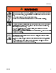
Warnings Warnings The following warnings are for the setup, use, grounding, maintenance, and repair of this equipment. The exclamation point symbol alerts you to a general warning and the hazard symbols refer to procedure-specific risks. When these symbols appear in the body of this manual or on warning labels, refer back to these Warnings. Product-specific hazard symbols and warnings not covered in this section may appear throughout the body of this manual where applicable.
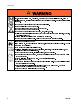
Warnings WARNING SKIN INJECTION HAZARD High-pressure fluid from gun, hose leaks, or ruptured components will pierce skin. This may look like just a cut, but it is a serious injury that can result in amputation. . • Do not spray without tip guard and trigger guard installed. • Engage trigger lock when not spraying. • Do not point gun at anyone or at any part of the body. • Do not put your hand over the spray tip. • Do not stop or deflect leaks with your hand, body, glove, or rag.
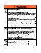
Warnings WARNING THERMAL EXPANSION HAZARD Fluids subjected to heat in confined spaces, including hoses, can create a rapid rise in pressure due to the thermal expansion. Over-pressurization can result in equipment rupture and serious injury. • Open a valve to relieve the fluid expansion during heating. • Replace hoses proactively at regular intervals based on your operating conditions.
Warnings WARNING EQUIPMENT MISUSE HAZARD Misuse can cause death or serious injury. • Do not operate the unit when fatigued or under the influence of drugs or alcohol. • Do not exceed the maximum working pressure or temperature rating of the lowest rated system component. See in all equipment manuals. • Use fluids and solvents that are compatible with equipment wetted parts. See Technical Data in all equipment manuals. Read fluid and solvent manufacturer’s warnings.
Warnings WARNING ENTAGLEMENT HAZARD Rotating parts can cause serious injury. • Keep clear of moving parts. • Do not operate equipment with protective guards or covers removed. • Do not wear loose clothing, jewelry or long hair while operating equipment. • Equipment can start without warning. Before checking, moving, or servicing equipment, follow the and disconnect all power sources. Pressure Relief Procedure BURN HAZARD Equipment surfaces and fluid that is heated can become very hot during operation.
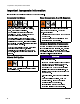
Important Isocyanate Information Important Isocyanate Information Isocyanates (ISO) are catalysts used in two component materials. Isocyanate Conditions Spraying or dispensing materials containing isocyanates creates potentially harmful mists, vapors, and atomized particulates. Read material manufacturer’s warnings and material MSDS to know specific hazards and precautions related to isocyanates.
Important Isocyanate Information Foam Resins with 245 fa Blowing Agents Some foam blowing agents will froth at temperatures above 90°F (33°C) when not under pressure, especially if agitated. To reduce frothing, minimize preheating in a circulation system. 332636D Changing Materials NOTICE Changing the material types used in your equipment requires special attention to avoid equipment damage and downtime. • When changing materials, flush the equipment multiple times to ensure it is thoroughly clean.
Models Models Reactor 2 E-30i All base systems include fluid inlet pressure and temperature sensors and Graco InSite™. For part numbers, see Accessories, page 12. Model Base Machine Maximum Fluid Working Pressure psi (MPa, bar) Approximate Output per Cycle (A+B) gal.
Models Reactor 2 E-XP2i All base systems include fluid inlet pressure and temperature sensors and Graco InSite™. For part numbers, see Accessories, page 12. Model Base Machine Maximum Fluid Working Pressure psi (MPa, bar) Approximate Output per Cycle (A+B) gal. (liter) Max Flow Rate gal/min (l/min) Total System Load † (Watts) Voltage (phase) Available Auxiliary Current at Volts, 60 Hz* No Air Compressor/Dryer E-XP2i with heat Air Compressor/Dryer E-XP2i with heat 272081 272091 3500 (24.
Approvals Approvals Note Intertek approvals apply to proportioning systems without hoses. Model 272079 272089 Proportioning System Approvals: Heated hoses provided with a system or sold individually are not approved by Intertek. Accessories Kit Number 15M483 9902471 Conforms to ANSI/UL Std. 73 Certified to CAN/CSA Std. C22.2 No. 68 272080 272081 272090 272091 15V551 24K207 24K333 24K336 24K337 24L911 24M174 24U174 24U176 24U177 Cables 121006 9902471 Conforms to ANSI/UL Std.
Supplied Manuals Supplied Manuals Related Manuals The following manuals are shipped with the Reactor. Refer to these manuals for detailed equipment information. Manuals are also available at www.graco.com. The following manuals are for accessories used with the Reactor.
Typical Installation, without circulation Typical Installation, without circulation Figure 1 * Shown exposed for clarity. Wrap with tape during operation.
Typical Installation, with circulation Typical Installation, with circulation Figure 2 * Shown exposed for clarity. Wrap with tape during operation.
Component Identification Component Identification Figure 3 Front View BA Component A Pressure Relief Outlet BB Component B Pressure Relief Outlet DG Drive Gear Housing DB Electrical Enclosure EM Electric Motor FA Component A Fluid Manifold Inlet FB Component B Fluid Manifold Inlet FM Reactor Fluid Manifold GA Component A Pressure Gauge GB Component B Pressure Gauge GG Generator, page 18 HA Component A Hose Connection HB Component B Hose Connection 16 HC MP PA PB PC PT SA SB SC TA TB Heated Hose Electric
Component Identification Figure 4 Back View CP Circulation Pump EC Electrical Cord Strain Relief FF Y-strainer (includes pressure gauge, temperature gauge, and pressure/temperature sensor) FH Booster Fluid Heater (not included with all models) FV Fluid Inlet Valve (A side shown) HE Heat Exchangers (heat exchanger coolant loop) 332636D HM LR MM SG VA VB VC Temperature Control Module (TCM) Cable Connections, page 31 ISO Pump Lubricant Reservoir Motor Control Module (MCM), page 28 Sight Glass Component A C
Component Identification Generator Figure 5 AF Air Filter BE Battery (not supplied) DF Diesel Fuel Filter EA 12V Charge Alternator EB Engine Coolant Expansion Bottle EE Engine ED Engine Oil Dipstick ER Radiator EX Exhaust FD Fuel Shutoff Solenoid FH Filter Housing FJ Fuel Injector FP Fuel Pump FS Diesel Fuel Fill Cap 18 FT GD GL HB HE HF OD OF OL OS RC RF ST TR WS Diesel Fuel Tank Generator Power Distribution Box Glow Plugs Heat Exchanger Coolant Expansion Bottle Heat Exchanger Heat Exchanger Coolant Fi
Component Identification Proportioner Control Panel PD PE PF* PG* PH* PJ* PK PL PM PN PP PR * Advanced Display Module (ADM), page 21 Engine Control Module, page 29 Component A Feed Pump Air Outlet Component B Feed Pump Air Outlet Agitator Air Outlet Gun Air Outlet Component A Feed Pump Air Regulator Component B Feed Pump and Agitator Air Regulator Gun Air Regulator Component A Feed Pump Pressure Gauge Component B Feed Pump and Agitator Pressure Gauge Gun Pressure Gauge Not for breathing air use.
Component Identification Air Compressor Select models are supplied with an air compressor and air dryer.
Component Identification Advanced Display Module The ADM display shows graphical and text information related to setup and spray operations. For detail on the display and individual screens, see Run Mode, page 53, or Setup Mode. Use the USB port on the ADM to download or upload data. For more information about the USB data, see USB Data, page 77. NOTICE To prevent damage to the softkey buttons, do not press buttons with sharp objects such as pens, plastic cards, or fingernails.
Component Identification Table 1 : ADM Keys and Indicators Key Function Press to startup or shutdown the system. Startup/Shutdown Key and Indicator Stop Soft Keys Navigation Keys Numeric Keypad Cancel Setup Press to stop all proportioner processes. This Is not a safety or emergency stop. Press to select the specific screen or operation shown on the display directly next to each key. • • Use to move from screen to screen.
Component Identification Figure 9 Back View CJ Flat Panel Mount (VESA 100) CK Model and Serial Number CL USB Port and Status LEDs CM CAN Cable Connection CN CP CR CS Module Status LEDs Accessory Cable Connection Token Access Cover Battery Access Cover Table 2 ADM LED Status Descriptions LED System Status USB Status (CL) ADM Status (CN) Conditions Green Solid Green Flashing Yellow Solid Yellow Flashing Green Flashing Yellow Solid Green and Yellow Flashing Green Solid Yellow Solid Red Steady Flashing
Component Identification ADM Display Details Power Up Screen The following screen appears when the ADM is powered up. It remains on while the ADM runs through initialization and establishes communication with other modules in the system. System Mode The current system mode is displayed at the lower left of the menu bar. Alarm/Deviation The current system error is displayed in the middle of the menu bar.
Component Identification Icons Screen Icons These are frequently used icons on the screens. The following descriptions explain what each icon represents. Icon Description Component A Component B Estimated Supply Material Hose Temperature Jog Mode Speed Engine Coolant Temperature Pressure Cycle Counter (press and hold) Advisory. See System Errors, page 71 for more information. Deviation. See System Errors, page 71 for more information Alarm.
Component Identification Electrical Enclosure AAA Temperature Control Module (TCM) AAB Motor Control Module (MCM) AAC Enclosure Fan AAD Circuit Breakers MP Main Power Switch 26 332636D
Component Identification Electrical Cabinet AAM Hose Breaker AAN Transformer AAP Load Center AAS Fan AAU Wiring Terminal Blocks 332636D 27
Component Identification Motor Control Module (MCM) Figure 10 MB 1 2 3 4 5 6 7 8 9 Description Module Status LEDs see LED Status Table CAN Communication Connections Motor Temperature Engine Coolant Temperature Heat Exchanger A Temperature Heat Exchanger B Temperature A Pump Output Pressure B Pump Output Pressure A Fluid Inlet Sensor B Fluid Inlet Sensor 10 11 12 13 14 15 16 Accessory Output Load Center Pump Cycle Counter Not Used Graco Insite™ Motor Power Output Main Power Input MCM Rotary Switch Pos
Component Identification Engine Control Module NOTICE To prevent damage to the softkey buttons, do not press buttons with sharp objects such as pens, plastic cards, or fingernails. For more information about the engine control module, see Appendix A: Engine Control Module, page 81. Icon Description On Auto Off Scroll Page Select Error Lamp Figure 11 332636D Function Start Engine Auto mode (not used) Stop all system processes. Is not a safety or emergency stop.
Component Identification Load Center LED Related Component Fuel Shutoff Solenoid (FS) D2 Starter (ST) Plugs D3 Glow (GL) Fan D4 Radiator (RF) D10 A Coolant Valve D1 F3 F4 K1 K2 K3 K4 MV 30 Radiator Fan Fuse Load Center Power Fuse Fuel Relay Starter Relay Glow Plug Relay Radiator Fan Relay Manual Valve Switch Color Green Red Green Green Red D12 B Coolant Valve Blue Coolant Green D14 Bypass Valve Valve D23 Manual Switch (MV) Red ON-State Fuel shutoff solenoid on the engine is open.
Component Identification Temperature Control Module (TCM) Cable Connections Figure 12 1 Power Input 2 Heater Overtemperature 3 CAN Communications Connections 4 Power Out (ISO) 5 Power Out (Res) 6 Power Out (Hose) 332636D 7 8 9 10 Module Status LEDs (see Advanced Display Module (ADM), page 21, Boost A Temperature (ISO) (CN) forHeater conditions Boost Heater B Temperature (RES) Hose Temperature 31
Component Identification Circuit Breakers P110 - Green/Yellow P100 - Green/Yellow P010 - Black Black Disconnect P040 - Red Blue P030 - Black Brown FAN P020 - Red Red Black P050 - Black P060 - Red CT01 P090 - Green/Yellow P080 - Red Note Not all wires are shown.
Component Identification Circuit Breaker Configuration Options Figure 14 Circuit Breakers Inside Proportioner Cabinet Ref. CB20 Size 50 A Component Heated Hose Improper configuration can result in electric shock. All electrical wiring must be done by a qualified electrician and comply with all local codes and regulations. See page 27 and 28 for correct circuit breaker configuration. See Circuit Breakers, page 32 for recommended circuit breaker configuration.
Overview Overview The system uses two coolant loops to use heat released from the engine to heat the A and B component material to the target temperatures defined on the ADM (PD). The engine coolant loop (gray) circulates heated coolant from the engine (EE), through the heat exchanger (HE), radiator (ER), and back to the engine. Coolant in the proportioner coolant loop (black) captures heat from the engine coolant loop inside the heat exchanger (HE) near the radiator.
Overview The proportioner coolant loop circulates coolant through secondary heat exchangers (HE) located on the back of the proportioner to heat the A and B component material before the material is pressurized in the proportioner pumps (PA, PB). After the A and B material has been heated in the heat exchangers, the material enters the fluid manifold (FM) and heated hose.
Overview Coolant only flows through the secondary heat exchangers when the heat exchanger control valves (VA, VB) are open and the A and B component temperatures are below the target temperatures set on the ADM. See Fig 18. When the control valves (VA, VB) close, the A and B material has reached target temperature. Coolant flows through the bypass control valve (VC), circulation pump (CP), sight glass (SG), proportioner coolant fill bottle (HF), and back to the heat exchanger in the engine coolant loop.
Setup 3. Do not expose Reactor to rain or below 20°F (-7°C). Setup NOTICE Proper system setup, startup, and shutdown procedures are critical to electrical equipment reliability. The following procedures ensure steady voltage. Failure to follow these procedures will cause voltage fluctuations that can damage electrical equipment and void the warranty. Do not remove or separate the proportioner, engine assembly, or power distribution box from the pallet.
Setup Trailer Setup Guidelines Route exhaust system away from combustible materials to prevent materials from igniting or gas recirculation into a wall, ceiling, or a concealed space. Provide exhaust system guards to prevent burns. NOTICE 2. Provide radiator exhaust for Reactor. Use a 400 in.2 (258,064 mm2) minimum louver. 3. Provide air duct to connect radiator exhaust to louver. 4. Provide a 400 in.2 ( 258,064 mm2) minimum fresh air intake louver near the generator. 5. Remove red exhaust cap. 6.
Setup 3. Remove fuel tank from the pallet. a. Remove the mounting screws, supports, and It is only possible to install a wall between the spacers. proportioner and generator for systems without an air b. Disconnect inlet and outlet fuel lines from the compressor. fuel tank. c. Use two people to lift fuel tank off of the pallet • Temperature condition the trailer space where and place where the fuel fill spout is easily chemical is stored. Check with chemical accessible.
Setup Figure 22 Top View With Wall Figure 23 Side View With Wall 40 332636D
Setup Connect Battery Improper battery installation or maintenance may result in electric shock, chemical burns, or explosion. Battery maintenance must only be performed or supervised by personnel knowledgeable of batteries and the required precautions. Keep unauthorized personnel away from batteries. See Technical Specifications, page 90 for battery requirements and recommended battery size. 1. Secure battery (not supplied) to bracket with strap. Engine Starter Connections Figure 25 3.
Setup General Equipment Guidelines Maintain and inspect the generator, air compressor, and other equipment per the manufacturer recommendations to avoid an unexpected shutdown. Unexpected equipment shutdown will cause voltage fluctuations that can damage electrical equipment. 5. Connect air lines to proportioner. Ensure components are properly connected to correct location.
Setup Connect Pressure Relief Lines Do not operate Reactor without all covers and shrouds in place. 1. Connect high pressure hose (R) to relief fittings (BA, BB) of both PRESSURE RELIEF/SPRAY valves. Route hose back to component A and B drums. See Typical Installation, with circulation, page 15. 2. Secure supplied bleed tubes (N) in grounded, sealed waste containers (H). See Typical Installation, without circulation, page 14. Recommended: Alternately: 2. Assemble heated hose sections, FTS, and whip hose.
Setup 5. Connect quick-disconnect pin fitting to 4 ft air hose, shipped loose. Connect other hose end to the gun air hose in the heated hose bundle. Push pin fitting into the lowest air panel outlet (PJ). Close gun fluid manifold valves A and B Connect Whip Hose to Gun Or Gun Fluid Manifold See hose manual for proper connections. Pressure Check Hose Figure 28 See hose manual. Pressure check for leaks. If no leaks, wrap hose and electrical connections to protect from damage.
Setup Grounding The equipment must be grounded to reduce the risk of static sparking and electric shock. Electric or static sparking can cause fumes to ignite or explode. Improper grounding can cause electric shock. Grounding provides an escape wire for the electric current. • Reactor System: System must be grounded with an appropriately sized conductor to the trailer or vehicle chassis or, if stationary, to true earth ground. Remove bolt and braided cable from pallet.
Setup Supply Wet Cups With Throat Seal Liquid (TSL) • Check felt washers in packing nut/wet-cup (S) daily. Keep saturated with Graco Throat Seal Liquid (TSL), Part No. 206995, to prevent material from hardening on displacement rod. Replace felt washers when worn or contaminated with hardened material. Component B (Resin) Pump: Pump rod and connecting rod move during operation. Moving parts can cause serious injury such as pinching or amputation. Keep hands and fingers away from wet-cup during operation.
Operation Operation 1. Turn the main power switch ON. The Graco logo will display until communication and initialization is complete. 3. Verify the machine is active and the System Status LED is illuminated green, see Advanced Display Module (ADM), page 21. If the System Status LED is not green, press the ADM Power On/Off (A) button . The System Status LED will illuminate yellow if the machine is disabled. Initial System Setup 2. Press the on/off button .
Operation Register and Activate the Graco Insite 1. Go to www.GracoInSite.com, click on “InSite Login, then follow the instructions on the screen. 2. Find and record the 15 digit serial number from the cellular box below. Serial No. Verify Module Status To check the status of the cellular module, locate the status LEDs on the module then refer to the following chart.
Operation Setup Mode The ADM will start in the Run screens at the Home screen. From the Run screens, press to access the Setup screens. The system defaults with no password, entered as 0000. Enter the current password then press . Press to navigate through the Setup Mode screens. Set Password Set a password to allow Setup screen access, see Advanced Screen 1 — General, page 50. Enter any number from 0001 to 9999.
Operation Advanced Setup Screens Advanced setup screens enable users to set units, adjust values, set formats, and view software information to scroll through the Advanced setup screens, Once in the desired for each component. Press Advanced setup screen, press to access the fields and make changes. When changes are complete press to exit edit mode. Note Users must be out of edit mode to scroll through the Advanced setup screens.
Operation System 1 Recipes Use this screen to set the activation pressure for the Pressure Imbalance Alarm and Deviation, enable or disable diagnostic screens, set the maximum and minimum drum volume, and enable drum alarms. Use this screen to add recipes, view saved recipes, and enable or disable saved recipes. Enabled recipes can be selected at the Home Run Screen. 24 recipes can displayed on the three recipe screens.
Operation Add Recipe 2. Use to highlight the next field and use the number pad to enter a value. Press to save. 1. Press and then use to select a Enable or Disable Recipes recipe field. Press to enter a recipe name (maximum 16 characters). Press to clear the 1. Press and then use to select the old recipe name. recipe that needs to be enabled or disabled. 2. Use to highlight the enabled check box. Press to enable or disable the recipe.
Operation Run Mode The ADM will start in the Run screens at the “Home” screen. Press Mode screens. . Or press to access the Setup screens. to navigate through the Run Home — System Off Home — System With Error This is the home screen when the system is off. This screen displays actual temperatures, actual pressures at the fluid manifold, jog speed, coolant temperature, and number of cycles. Active errors are shown in the status bar.
Operation Maintenance Use this screen to view daily and lifetime cycles or gallons that have been pumped and gallons or liters remaining in the drums. The lifetime value is the number of pump cycles or gallons since the first time the ADM was turned on. The daily value automatically resets at midnight. The manual value is the counter that can be manually reset. Press and hold to reset manual counter. All events and errors listed on this screen can be downloaded on a USB flash drive.
Operation System Events Use the table below to find a description for all system non-error events. All events are logged in the USB log files.
Operation Errors This screen shows the date, time, error code, and description of all errors that have occurred on the system. All errors listed on this screen can be downloaded on a USB flash drive. Recipes Use this screen to add recipes, view saved recipes, and enable or disable saved recipes. Enabled recipes can be selected at the Home Run Screen. 24 recipes can displayed on the three recipe screens. Job Data Use this screen to enter a job name or number.
Startup 3. Check fluid inlet filter screens. Before daily startup, ensure that the fluid inlet screens are clean. See Flush Inlet Strainer Screen, page 75. Startup To prevent serious injury, only operate Reactor with all covers and shrouds in place. NOTICE Proper system setup, startup, and shutdown procedures are critical to electrical equipment reliability. The following procedures ensure steady voltage.
Startup 6. Press start button on the engine control module twice to start the generator. Verify voltages are displayed on engine control module before moving to next step. The controller will automatically begin glow plug warming and crank operations. Allow engine to reach full operating speed. 8. For first startup of new system, set system settings on ADM in Setup Mode. See Initial System Setup, page 47. 9. For first startup of new system, adjust air settings to zero: a.
Startup 10. Start the air compressor, air dryer, breathing air, and other accessories. For systems with a supplied air compressor: start the air compressor by pressing start on the air compressor START box (CB). 11. Open the main air shutoff valve (CK). Circulation Through Reactor, page 61. If you need to circulate material through the heated hose to the gun manifold, see Circulation Through Gun Manifold, page 62. d. Turn both PRESSURE RELIEF/SPRAY valves (SA, SB) to SPRAY . e.
Startup g. Hold gun fluid manifold over two grounded waste containers. Open fluid valves A and B until clean, air-free fluid comes from valves. Close valves. Thermal expansion can cause overpressurization, resulting in equipment rupture and serious injury, including fluid injection. Do not pressurize system when preheating hose. a. Press to turn on hose heat zone. The Fusion AP gun manifold is shown. 14. Press to activate the system. b.
Fluid Circulation Fluid Circulation Circulation Through Reactor 3. Set PRESSURE RELIEF/SPRAY valves (SA, SB) to PRESSURE RELIEF/CIRCULATION . NOTICE To prevent equipment damage, do not circulate fluid containing a blowing agent without consulting with your material supplier regarding fluid temperature limits. Note Optimum heat transfer is achieved at lower fluid flow rates with temperature set points at desired drum temperature. Low temperature rise deviation errors may result.
Fluid Circulation Circulation Through Gun Manifold NOTICE To prevent equipment damage, do not circulate fluid containing a blowing agent without consulting with your material supplier regarding fluid temperature limits. Note Circulating fluid through the gun manifold allows rapid preheating of the hose. 1. Install gun fluid manifold (P) on accessory circulation kit (CK). Connect high pressure circulation lines (R) to circulation manifold. rated at the maximum working pressure of this equipment. 3.
Spraying 6. Verify that the engine temperature is at least up to the minimum operation temperature range. The fan will start running when the engine has reached maximum temperature. 7. Open fluid inlet valves. Spraying 1. Engage gun piston safety lock and close gun fluid inlet valves A and B. Fusion Probler 2. Attach gun fluid manifold. Connect gun air line. Open air line valve. 3. Adjust the gun air regulator on the proportioner control panel to desired gun air pressure. Do not exceed 130 psi (0.
Spraying 10. Open gun fluid inlet valves A and B. 12. Pull gun trigger to test spray onto cardboard. If necessary, adjust pressure and temperature to get desired results. Spray Adjustments Fusion Probler Flow rate, atomization, and amount of overspray are affected by four variables. • Too little pressure results in an uneven pattern, coarse droplet size, low flow, and poor mixing. Too much pressure results in excessive overspray, high flow rates, difficult control, and excessive wear.
Spraying Manual Hose Heat Mode If the system produces the T6DH sensor error hose alarm or the T6DT sensor error TCM alarm, use manual hose heat mode until the hose RTD sensor can be repaired. Do not use Manual Hose Mode for extended periods of time. The system performs best when the hose has a valid RTD and can operate in temperature control mode. If a hose RTD breaks, the first priority is to fix the RTD. Manual Hose Mode can help finish a job while waiting for repair parts. 4.
Spraying Disable Manual Hose Mode 1. Enter Setup Mode and navigate to System 2 Screen and deselect Enable Manual Hose Mode, or repair the hose RTD. 66 2. Manual hose mode is automatically disabled when the system detects a valid RTD sensor in the hose.
Shutdown Shutdown Immediate Shutdown 3. Set PRESSURE RELIEF/SPRAY valves (SA, SB) to PRESSURE RELIEF/CIRCULATION . NOTICE To avoid system damage, follow daily shutdown procedure. Use only for immediate shutdown. For immediate shutdown, press: 4. Relieve pressure. See Pressure Relief Procedure, page 69. 5. Press to park the Component A Pump. The park operation is complete when green dot goes out. Verify the park operation is complete before moving to next step. 6.
Shutdown 8. Close the main air shutoff valve. 10. Press to stop the engine. 11. Close all fluid supply valves. 9. Turn main power switch OFF. Allow engine cooling dwell time prior to shutting down the engine. 12. Engage gun piston safety lock then close fluid inlet valves A and B. To prevent electric shock do not remove any shrouds or open the electrical enclosure door. 240 V is still present in the system until the engine has stopped.
Pressure Relief Procedure Route fluid to waste containers or supply tanks. Pressure Relief Procedure 4. Turn PRESSURE RELIEF/SPRAY valves (SA, Follow the Pressure Relief Procedure whenever you see this symbol. This equipment stays pressurized until pressure is manually relieved. To help prevent serious injury from pressurized fluid, such as skin injection, splashing fluid and moving parts, follow the Pressure Relief Procedure when you stop spraying and before cleaning, checking, or servicing equipment.
Flushing Flushing To help prevent fire and explosion: • Flush equipment only in a well-ventilated area. • Do not spray flammable fluids. • Do not turn on heaters while flushing with flammable solvents. • Flush out old fluid with new fluid, or flush out old fluid with a compatible solvent before introducing new fluid. • Use the lowest possible pressure when flushing. • All wetted parts are compatible with common solvents. Use only moisture-free solvents.
System Errors System Errors Error Description A parameter critical to the process has reached System errors alert you of a problem and help a level requiring the prevent off-ratio spraying. When an error occurs the system to stop. The error information screen displays the active error alarm needs to be code and description. addressed immediately. The error code, alarm bell, and active errors will scroll A parameter critical in the status bar.
System Errors Troubleshoot Errors See system repair manual or visit help.graco.com for causes and solutions to each error code. To troubleshoot the error: 1. Press the soft key next to “Help With This Error” for help with the active error. Note 2. The QR code screen will be displayed. Scan the QR code with your mobile device to be sent directly to online troubleshooting for the active error code. Otherwise, manually navigate to help.graco.com and search for the active error.
Maintenance Maintenance Prior to performing any maintenance procedures, follow Pressure Relief Procedure, page 69. Preventative Maintenance Schedule Wiring Connections Tighten all screw-type wiring connections in the Electrical Enclosure (DB), Reactor cabinet, and air compressor control box (if supplied) monthly. Dust Protection Use clean, dry, oil-free compressed air to prevent dust buildup on control modules, control boards, fans, and motor (under shield).
Maintenance Clean Heat Sink Fins Engine Maintenance Keep heat sink fins clean at all times. Clean them using a dry cloth or compressed air. The engine instructions that accompany your unit detail specific procedures for maintenance of the engine. Following the engine manufacturer’s recommendations will extend engine work life. Note Do not use conductive cleaning solvents on the module.
Maintenance 3. Remove the screen (A) from the strainer manifold. Thoroughly flush the screen with compatible solvent and shake it dry. Inspect the Fuel quality is critical to the performance and to the screen. No more than 25% of the mesh should service life of the engine. Water in the fuel tank be restricted. If more than 25% of the mesh is can cause excessive wear to the fuel system. See blocked, replace the screen.
Maintenance Pump Lubrication System Check the condition of the ISO pump lubricant daily. Change the lubricant if it becomes a gel, its color darkens, or it becomes diluted with isocyanate. Gel formation is due to moisture absorption by the pump lubricant. The interval between changes depends on the environment in which the equipment is operating. The pump lubrication system minimizes exposure to moisture, but some contamination is still possible.
USB Data USB Data Each time a USB flash drive is inserted into the ADM USB port, a new folder named DATAxxxx is created. The number at the end of the folder name increases each time a USB flash drive is inserted and data is downloaded or uploaded. Note The ADM can read/write to FAT (File Allocation Table) storage devices. NTFS, used by 32 GB or greater storage devices, is not supported. USB Logs During operation, the ADM stores system and performance related information to memory in the form of log files.
USB Data Daily Log Blackbox Log File The daily log file name is 3–DAILY.CSV and is stored in the DATAxxxx folder. The daily log maintains a record of the total cycle and volume sprayed on any day that the system is powered up. The volume units will be the same units that were used in the Job Log.
USB Data Download Log Files Note System configuration setting files and custom language files can be modified if the files are in the UPLOAD folder of the USB flash drive. See System Configuration Settings File, Custom Language File, and Upload Procedure sections. Note If needed, set the number of days to download on the Advanced Setup Screen 3–USB in the ADM. USB log frequency can only be changed before logging occurs. 1. Insert USB flash drive into USB port. 2.
USB Data 1. If necessary, follow the to automatically generate the proper folder structure on the USB flash drive. The custom language file is a tab-delimited text file that contains two columns. The first column consists 2. Insert USB flash drive into USB port of computer. of a list of strings in the language selected at the time of download. The second column can be used 3. The USB flash drive window automatically opens. If it does not, open USB flash drive from within to enter the custom language strings.
Appendix A: Engine Control Module Appendix A: Engine Control Module Run Screens There are seven run screens on the engine control module: • Line-to-neutral voltage • Line-to-line voltage • Frequency • Engine Speed • Engine lifetime counter • Battery voltage Press to scroll through the run screens. Press to enter the Information screens. Run Screen Layout Inst Icon Instrumentation Units Alarm Icon Mode Icon Information Screens From the Run Screen, press to enter the information screens.
Appendix A: Engine Control Module Mode Icons Icon Description Details Stopped Engine is at rest and the unit is in stop mode. Auto Engine is at rest and the unit is in auto mode. Manual Engine is at rest and the unit is in manual run mode. Timer animation Engine is starting up. Running animation Engine is running. Instrumentation Icons A small icon is displayed in the instrumentation icon area to indicate what value is currently being displayed.
Appendix A: Engine Control Module Alarms There are two types of alarms that can occur on the system. Alarms are indicated by an icon the Run and Information screens. See the information screen to see the latest alarm. Warning When present on system, a warning alarm will stop the generator. Shutdown When present on system, a shutdown alarm will stop the generator.
Dimensions Dimensions 35 84 Figure 332636D
Dimensions Figure 36 Figure 37 332636D 85
Dimensions 38 Floor Mount Hole Pattern 86 Figure 332636D
Performance Charts Performance Charts Use these charts to help identify the proportioner that will work most efficiently with each mix chamber. Flow rates are based on a material viscosity of 60 cps. NOTICE To prevent system damage, do not pressurize the system above the line for the gun tip size being used. Proportioners For Foam 2000 (138) AR4242 (01) AR5252 (02) 1500 (103) PRESSURE psi (bar) AR6060 (03) 1000 (69) AR7070 (04) E-30i 500 (34) 0 332636D 5 (2.3) 10 (4.5) 15 (6.8) 20 (9.
Performance Charts Proportioners For Coatings Table 4 Fusion Air Purge, Round Pattern 3500 (241) 3000 (207) 2500 PRESSURE psi (bar) E-XP2i AR2020 (000) (172) AR2929 (00) 2000 (138) 1500 (103) AR4242 (01) 1000 (69) 500 (34) 0 0.5 1.0 (1.9) 1.5 (3.8) FLOW gal./min (l/min) 2.0 (5.7) (7.6) Table 5 Fusion Air Purge, Flat Pattern 3500 (241, 24.1) 3000 (207, 20.7) AF2929 (FTXX38 TIP) 2500 (174, 17.4) PRESSURE psi (bar) AF2020 (FTXX24 TIP) 2000 (138, 13.
Performance Charts Table 6 Fusion Mechanical Purge, Round Pattern 3500 (241, 24.1) E-XP2i 3000 (207, 20.7) XR2323 (RTM040) 2500 (174, 17.4) PRESSURE psi (bar) XR2929 (RTM040) 2000 (138, 13.8) MR3535 (RTM040) 1500 (103, 10.3) XR3535 (RTM055) 1000 (69, 6.9) MR4747 (RTM055) XR4747 (RTM055) 500 (35, 3.5) 0 0.5 (1.9) 1 1.5 (3.8) 2.0 (5.7) FLOW gal./min (l/min) (7.6) Table 7 Fusion Mechanical Purge, Flat Pattern 3500 (241, 24.
Technical Specifications Reactor 2 Elite Integrated Proportioning Systems Maximum Fluid Working Pressure E-30i E-XP2i Maximum Fluid Temperature E-30i E-30i with booster heater E-XP2i Maximum Output E-30i E-XP2i Maximum Heated Hose Length Length U.S. Metric 2000 psi 3500 psi 14 MPa, 140 bar 24.1 MPa, 241 bar 150°F 180°F 180°F 65°C 82°C 82°C 30 lb/min 2 gpm 13.5 kg/min 7.6 lpm 310 ft 94 m 0.0272 gal. 0.0203 gal. 0.1034 liter 0.
Recommended Battery Size 34 BC Group Number Length Width Height 10.25 in. 6.81 in. 7.88 in. Booster Heater Power E-30i E-30i with booster heat E-XP2i 260 mm 173 mm 200 mm None 4000 Watts 4000 Watts Rotary Vane Air Compressor Hydrovane Model V04 (PURS type), continuous run Part No. 025CK10 Pressure 140 psi Specifications Required Features 0.9 MPa, 9.6 bar) 16 cfm Thermal overload switch Safety Relief Valve Motor: Baldor Part No.
Weight E-30i E–30i with compressor and dryer E-30i with booster heat heat, E–30i with booster and dryer compressor, E-XP2i E–XP2i dryer with compressor and Wetted Parts Material 1750 lb 2200 lb 1800 lb 2250 lb 1800 lb 2200 lb 794 kg 998 kg 816 kg 1021 kg 816 kg 998 kg stainless steel, resistant zinc platedo-rings, carbonPTFE, steel,ultra-high brass, Aluminum, carbide, chrome, chemically molecular weight polyethylene
Graco Extended Warranty for Integrated Reactor® 2 Components Graco warrants all equipment referenced in this document which is manufactured by Graco and bearing its name to be free from defects in material and workmanship on the date of sale to the original purchaser for use. With the exception of any special, extended, or limited warranty published by Graco, Graco will, for a period of twelve months from the date of sale, repair or replace any part of the equipment determined by Graco to be defective.
Graco Information For the latest information about Graco products, visit www.graco.com. To place an order, contact your Graco Distributor or call to identify the nearest distributor. Phone: 612-623-6921 or Toll Free: 1-800-328-0211 Fax: 612-378-3505 All written and visual data contained in this document reflects the latest product information available at the time of publication. Graco reserves the right to make changes at any time without notice. For patent information, see www.graco.com/patents.