Repair-Parts Reactor 2 E-30 and E-XP2 Proportioning System 333024E Electric, Heated, Plural Component Proportioning System. For spraying polyurethane foam and polyurea coatings. For professional use only. Not approved for use in explosive atmospheres or hazardous locations. Important Safety Instructions. Read all warnings and instructions in this manual. Save these instructions. PROVEN QUALITY. LEADING TECHNOLOGY.
Contents Warnings ........................................................... 3 Important Isocyanate Information......................... 7 Models............................................................... 9 Approvals........................................................... 11 Accessories........................................................ 11 Supplied Manuals............................................... 12 Related Manuals ................................................ 12 Troubleshooting.......
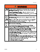
Warnings Warnings The following warnings are for the setup, use, grounding, maintenance and repair of this equipment. The exclamation point symbol alerts you to a general warning and the hazard symbol refers to procedure-specific risks. When these symbols appear in the body of this manual refer back to these Warnings. Product-specific hazard symbols and warnings not covered in this section may appear throughout the body of this manual where applicable.
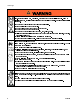
Warnings WARNING SKIN INJECTION HAZARD High-pressure fluid from gun, hose leaks, or ruptured components will pierce skin. This may look like just a cut, but it is a serious injury that can result in amputation. . • Do not spray without tip guard and trigger guard installed. • Engage trigger lock when not spraying. • Do not point gun at anyone or at any part of the body. • Do not put your hand over the spray tip. • Do not stop or deflect leaks with your hand, body, glove, or rag.
Warnings WARNING PRESSURIZED ALUMINUM PARTS HAZARD Use of fluids that are incompatible with aluminum in pressurized equipment can cause serious chemical reaction and equipment rupture. Failure to follow this warning can result in death, serious injury, or property damage. • Do not use 1,1,1-trichloroethane, methylene chloride, other halogenated hydrocarbon solvents or fluids containing such solvents. • Many other fluids may contain chemicals that can react with aluminum.
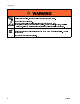
Warnings WARNING MOVING PARTS HAZARD Moving parts can pinch, cut or amputate fingers and other body parts. • Keep clear of moving parts. • Do not operate equipment with protective guards or covers removed. • Pressurized equipment can start without warning. Before checking, moving, or servicing equipment, follow the and disconnect all power sources. Pressure Relief Procedure BURN HAZARD Equipment surfaces and fluid that is heated can become very hot during operation.
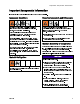
Important Isocyanate Information Important Isocyanate Information Isocyanates (ISO) are catalysts used in two component materials. Isocyanate Conditions Spraying or dispensing materials containing isocyanates creates potentially harmful mists, vapors, and atomized particulates. Read material manufacturer’s warnings and material MSDS to know specific hazards and precautions related to isocyanates.
Important Isocyanate Information Foam Resins with 245 fa Blowing Agents Some foam blowing agents will froth at temperatures above 90°F (33°C) when not under pressure, especially if agitated. To reduce frothing, minimize preheating in a circulation system. 8 Changing Materials NOTICE Changing the material types used in your equipment requires special attention to avoid equipment damage and downtime. • When changing materials, flush the equipment multiple times to ensure it is thoroughly clean.
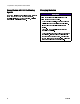
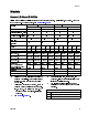
Models Models Reactor 2 E-30 and E-30 Elite All elite systems include fluid inlet pressure and temperature sensors, Graco InSite™, and Xtreme-Wrap 50 ft (15 m) head hose. For part numbers, see Accessories, page 11 E-30 Model Model 10 kW 15 kW 10 kW 15kW 272010 2000 (14, 140) 0.0272 (0.1034) 30 (13.5) 17,900 230 230 380 1Ø 3Ø∆ 3ØY 78 50 34 272011 2000 (14, 140) 0.0272 (0.1034) 30 (13.5) 23,000 230 230 380 1Ø 3Ø∆ 3ØY 100 62 35 272110 2000 (14, 140) 0.0272 (0.1034) 30 (13.
Models Reactor 2 E-XP2 and E-XP2 Elite All elite systems include fluid inlet pressure and temperature sensors, Graco InSite™, and Xtreme-Wrap 50 ft (15 m) head hose. For part numbers, see Accessories, page 11 Model E–XP2 Model 15 kW ★ Proportioner Maximum Fluid Working Pressure psi (MPa, bar) Approximate Output per Cycle (A+B) gal. (liter) Max Flow Rate gpm/min (l/min) Total System Load † (Watts) Configurable Voltage Phase E–XP2 Elite Model * Full Load Peak Current 272012 3500 (24.1, 241) 0.
Approvals Approvals Accessories Intertek approvals apply to proportioners without hoses. Proportioner Approvals: Kit Number 24U315 24U314 24T280 16X521 24N449 9902471 Conforms to ANSI/UL Std. 499 Certified to CAN/CSA Std. C22.2 No. 88 Note Heated hoses provided with a system or sold individually are not approved by Intertek.
Supplied Manuals Supplied Manuals The following manuals are shipped with the Reactor 2. Refer to these manuals for detailed equipment information. Manuals are also available at www.graco.com. Manual 333023 333091 333092 Description Reactor 2 E-30 and E-XP2 Operation Reactor 2 E-30 and E-XP2 Startup Quick Guide Reactor 2 E-30 and E-XP2 Shutdown Quick Guide Related Manuals The following manuals are for accessories used with the Reactor. Component Manuals in English: Manuals are available at www.graco.
Troubleshooting Troubleshooting 1. Press the soft key for help with the active error. Troubleshoot Errors There are three types of errors that can occur. Errors are indicated on the display as well as by the light tower (optional). Error Description A parameter critical to the process has reached a level requiring the system to stop. The alarm needs to be addressed immediately.
Troubleshooting Error Codes Note When an error occurs be sure to determine the code before resetting it. If you forget which error code occurred, see the Errors screen to view the last 200 errors, with date, time, and description. Error Location A1NM MCM Type Description Low Motor Current Cause Loose/broken connection. Bad Motor. A4DA Heater A High Current A Short circuit in heater wiring. Bad Heater. A4DB Heater B High Current B Short circuit in heater wiring. Bad Heater.
Troubleshooting Error Location A7DA Heater A A7DB Heater B A4NM MCM A7DH Hose 333024E Type Description Cause High Motor Current Short circuit of motor wiring. Solution Check wiring to the motor to ensure no bare wires are touching and that no wires are shorted to ground. Motor will not Remove pump gear rotate. housings from motor and check that motor shaft rotates freely in direction indicated on motor housing. Damaged gear Check pump gear trains train.
Troubleshooting Error Location A8DA Heater A A8DB Heater B Type Description No Current A No Current B A8DH Hose No Current Hose CACM MCM MCM Communication Error 16 Cause Tripped circuit breaker. Solution Visually check circuit breaker for a tripped condition. Loose/broken Check heater wiring for connection. loose wires. Tripped circuit Visually check circuit breaker. breaker for a tripped condition. Loose/broken Check heater wiring for connection. loose wires.
Troubleshooting Error Location CACT TCM Type Description TCM Communication Module does not have software. Error DADX MCM Pump Runaway DE0X Cycle Switch Error 333024E MCM Cause Solution Insert a system token into the ADM module and cycle the power. Wait until the upload is complete before removing the token. No 24 VDC supply Green light on each module to module. should be lit. If green light is not lit, check to make sure each CAN cable connection is tight.
Troubleshooting Error Location Description Cause EAUX ADM USB Busy EVUX ADM USB disabled USB drive has been inserted to the ADM. USB download/uploads are disabled. F9DX High Pressure/Flow Mix chamber is Cutback too large for set pressure. EVCH ADM MCM Type Manual Hose Mode Manual hose mode Enabled has been enabled in System Setup screen.
Troubleshooting Error Location L1BX ADM L1AX ADM MMUX USB P0AX 333024E MCM Type Description Cause Solution Low Chemical Level Low material level. Refill material and update A drum level on ADM Maintenance screen. Alarm can be disabled on the System Setup screen. Low Chemical Level Low material level. Refill material and update B drum level on ADM Maintenance screen. Alarm can be disabled on the System Setup screen.
Troubleshooting Error P0BX Location MCM P1FA MCM P1FB MCM P2FA MCM 20 Type Description Cause Pressure Imbalance Pressure B High difference between A and B material is greater than the defined value. Pressure imbalance is defined too low. Solution Ensure material flow is equally restricted on both material lines. Ensure that the pressure imbalance value, on the System Setup screen, is at an acceptable maximum pressure to prevent unnecessary alarms and abort dispenses. Out of material.
Troubleshooting Error P2FB P4AX Location MCM MCM Type Description Cause Low Inlet Pressure B Inlet pressure lower than defined value. Value defined too high. High Pressure A System pressurized before allowing heat to reach setpoint. Bad pressure transducer. E-XP2 system configured as E-30. P4BX MCM High Pressure B System pressurized before allowing heat to reach setpoint. Bad pressure transducer. E-XP2 system configured as E-30.
Troubleshooting Error P6AX Location MCM Type Description Pressure Sensor Error A Cause Loose/bad connection. Bad sensor. P6BX MCM Pressure Sensor Error B Loose/bad connection. Bad sensor. P6FA MCM Pressure Sensor Error Inlet A Inlet sensors not installed. Loose/bad connection. Bad sensor. 22 Solution Check to ensure the pressure transducer is properly installed and all wires are properly connected. Check if the error follows the transducer.
Troubleshooting Error Location P6FB MCM P7AX MCM 333024E Type Description Cause Inlet sensors not installed. Solution If inlet sensors are not installed, inlet sensors should be disabled on the System Setup screen. Loose/bad Check to ensure inlet connection. sensor is properly installed and all wires are properly connected. Bad sensor. Check if the error follows the inlet sensor. Disconnect inlet sensor cables from the MCM (connectors 8 and 9).
Troubleshooting Error P7BX Location MCM Type Description Cause Pressure Imbalance Pressure B High difference between A and B material is greater than the defined value. Pressure imbalance is defined too low. Out of material. Fluid leaking from heater inlet rupture disk. Feed system defective. T2DA Heater A Low Temperature A Flow is too high at current setpoint. Bad RTD or bad RTD placement against heater. Bad heater rod or loose heater wire.
Troubleshooting Error Location T2DB Heater B T2DH Hose T2FA MCM T2FB MCM 333024E Type Description Cause Solution Low Temperature B Flow is too high at Use a smaller mix chamber current setpoint. that is rated for the unit in use. If recirculating, decrease flow or decrease temperature setpoint. Bad RTD or bad Swap A and B heater output RTD placement cables and RTD cables and against heater. see if issue follows. If so, replace RTD. Bad heater rod or Confirm resistance of loose heater wire.
Troubleshooting Error Location Type Description T3CH Hose T3CT TCM TCM Cutback T3NM MCM MCM Cutback T4CM MCM High Temperature MCM 26 Hose Cutback Cause Hose current has been reduced because hose has been drawing current for an extended period. Solution Hose setpoint higher than A and B setpoints. Decrease hose setpoint. Hose FTS is in a colder environment than the rest of the hose. Expose FTS to the same environment as the rest of the hose. High ambient Ensure ambient temperature.
Troubleshooting Error Location T4DA Heater A T4DB Heater B T4CT 333024E TCM Type Description High Temperature TCM Cause High ambient temperature. Solution Ensure ambient temperature is below 120°F(48°C) before using the system. Enclosure fan not Ensure fan in electrical operating. enclosure is spinning. If it is not, check fan wiring or replace fan. Module fan not If a TCM fan error (WMI0) operating. has occurred, fan inside the module is not working properly.
Troubleshooting Error T4DH T4EA 28 Location Hose Heater A Type Description High Temperature Hose High Temperature Switch A Cause Hose portion exposed to an excessive heat source, like hot sun or coiled hose, can pass fluid more than 27°F (15°C) over hose temperature setting to the FTS. Setting the A or B setpoint much higher than hose setpoint can cause fluid more than 27°F (15°C) over hose temperature setting to reach the FTS. Overtemperature switch sensed a fluid temperature above 230°F (110°C).
Troubleshooting Error T4EB Location Heater B Type Description High Temperature Switch B T4NM MCM High Temperature Motor T6DA Sensor Error A 333024E Heater A Cause Solution Heater was delivered too much power, causing the overtemperature switch to open. RTD is not reading properly. After the heater cools down, replace RTD. Switch closes and the error can be cleared when the heater temperature falls below 190°F (87°C).
Troubleshooting Error Location Type Description T6DB Heater B T6DH Hose Sensor Error Hose T6DT TCM Sensor Error TCM 30 Sensor Error B Cause Solution Disconnected or Check all wiring and loose RTD cable or connection to RTD. connection. Bad RTD. Switch the RTD with another and see if the error message follows the RTD. Replace RTD if the error follows the RTD. Disconnected or Expose each hose RTD shorted RTD cable connection to check and in hose or bad FTS. retighten any loose connector.
Troubleshooting Error T8DA Location Heater A Type Description No Temperature Rise A Cause Bad RTD or bad RTD placement against heater. Bad heater rod or loose heater wire. T8DB Heater B No Temperature Rise B Started spraying before heater reached operating temperature. Bad RTD or bad RTD placement against heater. Bad heater rod or loose heater wire.
Troubleshooting Error Location V1IT TCM V2IT TCM Type Description Low Voltage CAN Low Voltage CAN V2MA TCM Low Voltage A V2MB TCM Low Voltage B V2MH TCM Low Voltage Hose V3IT High Voltage CAN TCM V3MA TCM 32 High Voltage A Cause Solution Bad 24 VDC power Check voltage of power supply. supply. Voltage should be 23-25 VDC. If out of tolerance, replace power supply. Bad 24 VDC power Check voltage of power supply. supply. Voltage should be 23-25 VDC.
Troubleshooting Error Location V3MB TCM Type Description High Voltage B V3MH TCM High Voltage Hose V4CM MCM High Voltage MCM V4IT High Voltage CAN TCM V4MA TCM High Voltage A V4MB TCM High Voltage B V4MH TCM High Voltage Hose 333024E Cause Solution Incoming line Ensure incoming system voltage is too high. power is wired properly. Verify voltage at each circuit breaker is between 195 and 264 VAC. Incoming line Ensure incoming system voltage is too high. power is wired properly.
Troubleshooting Error Location WMI0 TCM WBC0 MCM WSUX USB WXUD ADM WXUU ADM 34 Type Description Cause Solution Incorrect software Insert a system token into the ADM module and cycle version. the power. Wait until the upload is complete before removing the token. MCM does not If V1CM also exists, see have line voltage. troubleshooting for V1CM. The software version cannot be read if the MCM does not have line voltage.
Troubleshooting System Before performing any troubleshooting procedures: 1. Relieve Pressure. See Pressure Relief Procedure, page 42. 2. Turn main power switch OFF. 3. Allow equipment to cool. Problem Reactor ADM does not turn on. Electric motor does not operate. Electric motor runs erratically. 333024E Cause No power. Failed 24 V power supply. Failed surge protector. Loose connections. Tripped circuit breaker (CB02). Shorted windings. Failed motor bearing. Solution Turn main power switch ON.
Troubleshooting Problem Cooling fans not working. Pump output low. Fluid leak in pump packing nut area. No pressure on one side. 36 Cause Loose wire. Fan blade obstructed. Defective fan. Obstructed fluid hose or gun; fluid hose ID too small. Worn piston valve or intake valve in displacement pump. Pressure setpoint too high. Worn throat seals. Fluid leaking from heater inlet rupture disk (372). Solution Check. See Electrical Schematics, page 89. Remove obstruction. Replace.
Troubleshooting Hose Heat System Before performing any troubleshooting procedures: 1. Relieve Pressure. See Pressure Relief Procedure, page 42. 2. Turn main power switch OFF. 3. Allow equipment to cool. Problem Hose heats but heats slower than usual or it does not reach temperature. Hose does not maintain temperature while spraying. Hose temperature exceeds setpoint. 333024E Cause Solution Ambient temperature is too cold. Relocate hoses to a warmer area or recirculate heated fluid through the hose.
Troubleshooting Problem Erratic hose temperature. Hose does not heat. 38 Cause Faulty FTS connections. Solution Verify that all FTS connections are snug and that pins of connectors are clean. Unplug and re-plug FTS wires along length of hose, cleaning off any debris. FTS not installed correctly. FTS should be installed close to end of hose in same environment as gun. Verify FTS installation, see Repair Fluid Temperature Sensor (FTS), page 64. FTS failed.
Troubleshooting Problem Cause Solution Hoses near Reactor are warm, but Shorted connection or failed hose With power off, check the hose hoses downstream are cold. heating element. resistance with and without the whip hose attached. With the whip hose attached, the reading should be less than 3 ohm. Without the whip hose attached, the reading should be OL (open loop). See Check Hose Heat Connectors, page 63. Low hose heat. A and B temperature setpoints too Increase A and B setpoints. Hose low.
Troubleshooting Primary Heater Before performing any troubleshooting procedures: 1. Relieve Pressure. See Pressure Relief Procedure, page 42. 2. Turn main power switch OFF. 3. Allow equipment to cool. Problems Try the recommended solutions in the order given for each problem, to avoid unnecessary repairs. Also, determine that all circuit breakers, switches, and controls are properly set and wiring is correct before assuming there is a problem. Problem Cause Primary Heater(s) does not heat.
Troubleshooting Graco InSite Problem No module status LEDs are illuminated. Cause No power to cellular module. Solution Turn Reactor ON. Ensure unit is properly installed. Verify 24V at output of the power supply. Make sure the M8, 4–pin to M12, 8–pin cable is installed between cellular module and power supply. Has not identified GPS location Still identifying location. Wait a few minutes for the unit to (green module status LED identify the location. Unable to identify location.
Pressure Relief Procedure Route fluid to waste containers or supply tanks. Pressure Relief Procedure 4. Turn PRESSURE RELIEF/SPRAY valves (SA, Follow the Pressure Relief Procedure whenever you see this symbol. This equipment stays pressurized until pressure is manually relieved. To help prevent serious injury from pressurized fluid, such as skin injection, splashing fluid and moving parts, follow the Pressure Relief Procedure when you stop spraying and before cleaning, checking, or servicing equipment.
Shutdown Shutdown 4. Press to park the Component A Pump. The park operation is complete when green dot goes out. Verify the park operation is complete before moving to next step. Shutdown system to avoid electric shock. All electrical wiring must be done by a qualified electrician and comply with all local codes and regulations.
Shutdown 8. Close all fluid supply valves. 9. Engage gun piston safety lock then close fluid inlet valves A and B.
Flushing Flushing To avoid fire and explosion: • Flush equipment only in a well-ventilated area. • Do not turn on heaters until fluid lines are clear of solvent. • Flush out old fluid with new fluid, or flush out old fluid with a compatible solvent before introducing new fluid. • Use the lowest possible pressure when flushing. • All wetted parts are compatible with common solvents. Use only moisture-free solvents.
Repair Repair Repairing this equipment requires access to parts that may cause electric shock or other serious injury if work is not performed properly. Be sure to shut off all power to equipment before repairing. Before Beginning Repair NOTICE Proper system setup, startup, and shutdown procedures are critical to electrical equipment reliability. The following procedures ensure steady voltage.
Repair Change Pump Lubricant Check the condition of the ISO pump lubricant daily. Change the lubricant if it becomes a gel, its color darkens, or it becomes diluted with isocyanate. Gel formation is due to moisture absorption by the pump lubricant. The interval between changes depends on the environment in which the equipment is operating. The pump lubrication system minimizes exposure to moisture, but some contamination is still possible.
Repair Remove Pump Pump rod and connecting rod move during operation. Moving parts can cause serious injury such as pinching or amputation. Keep hands and fingers away from connecting rod during operation. Note 1. 2. 3. 4. 5. 6. See manual 309577 for pump repair instructions. Press to stop the pumps. Turn off heat zones. 8. Route fluid to waste containers or supply tanks. Turn PRESSURE RELIEF/SPRAY valves (SA, Flush pump. SB) to PRESSURE RELIEF/CIRCULATION Press to park the pumps in the down position. .
Repair Note Use drop cloth or rags to protect Reactor and surrounding areas from spills. Note Steps 9–11 apply to pump A. To disconnect pump B, go to steps 12 and 13. 9. Disconnect fittings at fluid inlet (C) and outlet (D). Also disconnect steel outlet tube from heater inlet. 10. Disconnect tubes (T). Remove both tube fittings (U) from wet-cup. 11. Loosen locknut (G) by hitting firmly with a non-sparking hammer. Unscrew pump far enough to expose rod retaining pin. Push retaining wire clip up. Push pin out.
Repair 11. Apply thin film of TSL to barbed fittings. Using two hands, support tubes (T) while pushing straight onto barbed fittings. Secure each tube with a wire tie between two barbs. Note Do not let tubes kink or buckle. 12. Reconnect fluid inlet (C). 13. Purge air and prime the system. See Reactor operation manual. Repair Drive Housing Removal Figure 5 7. Start threading pump into bearing housing (M). When pin holes align, insert pin. Pull retaining wire clip down. 8.
Repair 7. Perform Pressure Relief Procedure, page 42. 8. Remove the system frame from the floor and L-brackets. NOTICE Do not drop gear cluster (104) when removing drive housing (102). Gear cluster may stay engaged in motor front end bell or drive housing. 14. Remove screws (112, 119) and washers (114) and pull drive housing (102) off motor (101). Note The A side drive housing includes cycle counter switch (121). If replacing this housing, remove screws (122) and switch.
Repair Installation 1. Apply heavy duty extreme pressure grease liberally to washers (107, 108, 118), all gears, and inside drive housing (102). 2. Install one bronze washer (108) in drive housing, then install steel washers (107, 118) as shown. 3. Install second bronze washer (108) on gear cluster (104) and insert gear cluster in drive housing. Note Drive housing crankshaft must be in line with crankshaft at other end of motor. 4. Push drive housing (102) onto motor (101).
Repair Repair Electric Motor Removal NOTICE Be careful not to drop or damage the motor. The motor is heavy and may require two people to lift. 1. Remove the system frame from the floor and L-brackets. Installation 2. 3. 4. 5. 6. 1. Place motor on unit. Thread motor cables into conduit as before. See Electrical Schematics, page 89. 2. Fasten motor with screws (25) until screws are fully threaded in frame.
Repair new circuit breaker. Insert wires and tighten down all screws. Repair Circuit Breaker Module 1. See Before Beginning Repair, page 46. 2. Using an ohmmeter, check for continuity across circuit breaker (top to bottom). If no continuity, trip breaker, reset, and retest. If still no continuity, replace breaker as follows: a. Refer to Electrical Schematics, page 89, and circuit breaker table. b. Follow Shutdown instructions. See Shutdown, page 43. c.
Repair Replace Fluid Inlet Sensor 5. Replace sensor (602). Replace Pressure Transducers Note For Elite models only. 1. Perform Shutdown, page 43. 2. Perform Pressure Relief Procedure, page 42. 3. Disconnect inlet sensor cable from the fluid inlet assembly. Inspect cable for damage and replace if necessary. See Electrical Schematics, page 89. 1. Perform Shutdown, page 43. 2. Perform Pressure Relief Procedure, page 42. 3. Disconnect transducer cables (405) from #6 and #7 connectors on the MCM. 4.
Repair Replace Fans Shutdown system to avoid electric shock. To avoid burns, do not perform maintenance on the fan until the system has reached ambient temperature. Replace Motor Fan 1. Perform Shutdown, page 43. 2. Open cabinet door and disconnect fan cables from terminal blocks. See Electrical Schematics, page 89. 3. Remove four screws (21) from motor cover (11). If necessary, fold frame (1) to remove motor cover (10). See Repair Drive Housing, page 50, steps 1–10. 4. Cut tie wraps to remove cable. 5.
Repair Replace Electrical Enclosure Fan 1. Perform Shutdown, page 43. 2. Open electrical enclosure door (401). Loosen four nuts (421) and remove fan (404). 3. Install new fan (404) in reverse order of disassembly so that the fan blows out of the electrical enclosure.
Repair Replace Transformer Fan 1. Perform Shutdown, page 43. 2. Remove four bolts (23) and shroud (10). 3. Remove bolt (20) on top of the heater junction box (48). 4. Disconnect fan and transformer connections from terminal blocks. Connections are on left side labeled: V+, V-, 1, 2, 3, and 4. 5. Remove four nuts (27) holding metal transformer cover (8) to frame. Carefully remove cover while sliding wires through hole in cover. 6. Remove four screws (23), washers (29), and fan (32). 7.
Repair Repair Primary Heater Replace Heater Element 8. Wait for heater to cool. 9. Remove four bolts (23) and shroud (10). 1. Press to stop the pumps. 2. Turn off heat zones. 3. Flush pump. 10. Remove screw (20) and lower din rail cover (48). 4. Press to park the pumps in the down position. 11. Disconnect heater wires: The park operation is complete when green dot a. A Side: Disconnect A side heater wires, goes out.
Repair 13. Remove nuts (27) and transformer cover (8). Cover transformer with plastic sheet or cardboard. 14. Disconnect overtemperature switches (209) from cable. 15. Loosen ferrule nut (N). Remove RTD (212) from heater housing. Do not remove adapter (206) unless necessary. If adapter must be removed, ensure that mixer (210) is out of the way when replacing adapter. 16. Disconnect inlet and outlet fluid tubes from heater. 17. Remove two bolts (23) and lift heater over transformer. 18.
Repair Repair Overtemperature Switch 1. 2. 3. 4. Perform Shutdown, page 43. Wait for heaters to cool. Remove heater cover (10). Disconnect overtemperature switches (209) from cable (46). Test across spade terminals with ohmmeter. a. If the resistance approximately 0 ohms, the overtemperature switch needs to be replaced. Go to step 5. b. If the resistance approximately 0 ohms, inspect cable (46) to ensure it is not cut or open. Reconnect the overtemperature switch (209) and cable (46).
Repair Replace RTD 1. 2. 3. 4. 5. 6. 7. 8. Perform Shutdown, page 43. Wait for heater to cool. Remove heater cover (10). Cut cable ties around the woven wrap with the RTD cable (212). Disconnect RTD cable(212) from TCM (453). Loosen ferrule nut (N). Remove RTD (212) from heater housing (201), then remove RTD housing (H). Do not remove the adapter (206) unless necessary. If adapter must be removed, ensure that mixer (210) is out of the way when replacing the adapter.
Repair Repair Heated Hose Refer to the heated hose manual 309572 for hose replacement parts. Check Hose Heat Connectors 1. Perform Shutdown, page 43. 5. If the FTS is not reading properly at the end of the hose, connect FTS directly to RTD cable (C) at the manifold. 6. If the FTS reads properly at the manifold but not at the end of the hose, check cable (C) connections. Verify they are tight. Note Whip hose must be connected. 2. Disconnect hose connector (V) at Reactor, see Fig. 13. 3.
Repair Repair Fluid Temperature Sensor (FTS) Installation The Fluid Temperature Sensor (FTS) is supplied with the system. Install FTS between main hose and whip hose. See Heated Hose manual 309572 for instructions. Figure 16 Test/Removal 1. Perform Shutdown, page 43. 2. Remove tape and protective covering from FTS. Disconnect hose cable (F). 3. If FTS is not reading properly at the end of the hose, see Check RTD Cables and FTS, page 63. 4. If FTS fails, replace FTS. 64 a.
Repair Transformer Primary Check See Electrical Schematics, page 89. 1. Check wires and transformer: a. See Shutdown, page 43. b. Shut off CB05. c. Use an ohmmeter to test for continuity between terminals 2 and 4 of CB05. If there is no continuity, check transformer. 2. Check transformer: a. See Shutdown, page 43. b. Remove lower shroud. c. Locate the two smaller (10 AWG) wires, labeled 1 and 2, coming out of transformer. Trace these wires back to terminal blocks TB15 and TB16. d.
Repair Replace Transformer 1. 2. 3. 4. Perform Shutdown, page 43. Remove four bolts (23) and shroud (10). Remove lower dinrail cover (48). Disconnect fan and transformer connections from terminal blocks. Connections are on left side labeled: V+, V-, 1, 2, 3, and 4. 5. Remove four nuts (27) holding metal transformer cover (8) to frame. Carefully remove cover while sliding wires through hole in cover. 6. Remove nuts (27) and transformer (17). 7. Install transformer (17) in reverse order.
Repair Replace Power Supply 1. Perform Shutdown, page 43. 2. Disconnect input and output cables from both sides of the power supply. See Electrical Schematics, page 89. 3. Insert a flat head screw driver in the mounting tab on the bottom of the power supply to remove from the din rail. 4. Install new power supply (535) in reverse order. Figure 20 Surge Protector Replace Advanced Display Module (ADM) 1. Loosen four screws (70) on inside of electrical enclosure door (61).
Repair Replace Motor Control Module (MCM) 1. Perform Shutdown, page 43. 2. Disconnect connectors from MCM (63). Disconnect two power cables. See Electrical Schematics, page 89. 3. Remove nuts (91) and MCM (63). 4. Set rotary switch. 2= E–30 and 3= E-XP2. 5. Replace MCM in enclosure. 6. Connect cables to MCM. See Electrical Schematics, page 89. Figure 22 Replace MCM Replace Temperature Control Module (TCM) 1. 2. 3. 4. 5. Perform Shutdown, page 43. Open electrical enclosure door (61).
Parts Parts Proportioners 333024E 69
Parts 1 2 3 70 Apply anaerobic polyacrylate pipe sealant to all non-swiveling pipe threads. Apply grease to tube fitting threads. Torque to 43 ft-lbs (58 N•m). Safety and warning labels are from label sheet (68).
Parts Ref 1 2 Part - - - - - 3 246995 4 5 16X531 24U843 24U842 6 24U704 7 16W654 8 9 24R684 261821 10 11 12 13 24U841 16W765 16W764 24U837 24U838 24U839 24U840 14 15 17 24U834 24U833 24U836 24U835 15K742 18 19 15B456 125643 20 119865 16 333024E Description FRAME ENCLOSURE, electrical; see Electrical Enclosure, page 82 BOTTLE, assembly, complete BRACKET, tsl, bottle HEATER, 10kw, 2 zone, RTD; see Fluid Heater, page 78 HEATER, 7.
Parts Ref 21 22 23 24 25 26 27 28 29 30 31 32 33 33a 33b 33c 33d 34 35 36 37 38 39 40 41 42★ 43★ 72 Part Description 118444 SCREW, mch, slot hex wash hd; 1/2 in. x #10–24 117683 SCREW, mch, phil pan hd; 1.5 in. x #6–32 113796 SCREW, flanged, hex hd; 3/4 in. x 1/4–20 112731 NUT, hex, flanged 111800 SCREW, cap, hex hd; 7/32 in. x 5/16–18 111218 CAP, tube, square 110996 NUT, hex, flange head 104859 SCREW, tapping pnhd; 5/16 in.
Parts Ref 44★ 45★ 46 47 48 49 50 51 52 53 54 55 56 57 58 333024E Part Description 24R725 BRIDGE, plug-in jumper, ut35 106569 TAPE, electrical 24T242 CABLE, over-temp, 10 kW Reactor 24P970 CABLE, over-temp, 15 kW Reactor 104765 PLUG, pipe headless 16V268 COVER, top, dinrail 15Y118 LABEL, made in the USA 24V150 PROPORTIONER, module, E-30; see Proportioner Module, page 76 24V151 PROPORTIONER, module, E-XP2; see Proportioner Module, page 76 24U321 KIT, asm, pair, elite, reactor; see Fluid Inlet Ki
Parts Ref 59★ 60 61 62 63 64★ 65★ 67★ 68 70 71 72 73 74 75 79★ 81 82 83★ 84★ 85 88 89 74 Part Description 16U530 MODULE, system surge protector (spare) 15G349 COVER, drive, plastic 16W766 COVER, control, box 16W596 LATCH, door 24U832 MODULE, MCM 24U831 MODULE, MCM 206995 FLUID, tsl, 1 qt. 206994 FLUID, tsl 8 oz bottle 114225 TRIM, edge protection; 1.6 ft (0.48 m) 16X250 LABEL, identification 127296 SCREW, mchn, pnh, w/ext tooth wash; M4 x 0.
Parts Ref 90 91 92 93★ 94 95 96★ 97★ Part Description 16W213 LABEL, branding, reactor 115942 NUT, hex, flange head 15D906 SUPPRESSOR, round snap ferrite .260 127368 SLEEVE, split, wire, 1.50 ID 127377 TIE, cable, 6 in. 16X154 LABEL, InSite 333091 MANUAL, quick guide, startup 333092 MANUAL, quick guide, shutdown Quantity 272010 272011 272012 272110 272111 272112 2 2 2 2 2 2 1 1 1 1 1 1 1 1 ▲ Replacement Warning labels, signs, tags, and cards are available at no cost. ★ Not shown.
Parts Proportioner Module 24V150, Module for E-30 24V151, Module for E-XP2 1 2 Torque to 190–120 in-lbs (21–24 N•m). Lubricate threads with ISO oil or grease. Assemble pump cylinders flush to one full thread under-flush of housing surface. 3 Apply grease to all gear teeth proportionally, motor pinion and drive housing. 4 Torque to 20–30 ft-lbs (27–40.6 N•m). 5 Crankshaft must be in line with crankshaft at other end of motor. 6 Torque to 70–80 ft-lbs (95–108 N•m). 7 Flat side faces up.
Parts 24V150 E-30 24V151 E-XP2 MOTOR, brushless, double ended, 2 HP 1 1 --- HOUSING, drive, Mark VII 2 2 257355 HOUSING, bearing 245927 HOUSING, bearing 2 104 287290 KIT, repair, gear 2 2 105 241279 KIT, rod, connecting 2 2 106★ 245971 PUMP, displacement A 245972 PUMP, displacement A 1 107 114699 WASHER, thrust; copper colored 2 2 108 114672 WASHER, thrust; steel colored 4 4 110 183169 SPRING, retaining 2 2 111 183210 PIN, str, hdls 2 2 112 15C753 SC
Parts Fluid Heater 24U843 — 10kW, 2–zone 24U842 — 7.5 kW, 1–zone 1 Torque to 120 ft-lbs (163 N•m). 2 Torque to 23 ft-lbs (31 N•m). 4 Torque to 40 ft-lbs (54 N•m). Apply thermal paste. 5 Apply pipe sealant and PTFE tape to all non-swiveling threads and threads without o-rings. 3 6 7 78 Apply lithium grease lubricant to o-rings before assembling in block (1). Remove tape from probe tip and Orientate sensor as shown. Insert probe until it bottoms on heating element.
Parts Ref 201 Part 15J090 Description HEATER, machined, 1 zone HEATER, machined, dual zone 1 202 15K825 124132 O-RING 4 FITTING, plug, hollow, hex, 1-3/16 sae 4 3 5 FITTING, adapter, sae-orb x jic 4 2 3 203 204 15H305 121309 24U843 24U842 1 205 15H304 FITTING, plug 9/16 sae 2 206 ADAPTER, 9/16 x 1/8 2 1 207 15H306 120336 2 1 208 16A110 O-RING, packing HEATER, immersion, 2550W, 230V 4 3 SWITCH, over temperature MIXER, immersion heater 1 1 4 3 FITTING, compression 2 1
Parts Fluid Manifold 24U844 1 2 3 80 Torque to 355–395 in.-lbs (40–44.6 N●m) Apply sealant (113500) to threads. Valve must be closed with handle position as shown on drawing. 4 5 ** Apply PTFE tape and thread sealant to gauge threads. Apply grease on valve. Apply PTFE tape or thread sealant to tapered threads.
Parts 24U844, Fluid Manifold Ref 401 402★ 402a★ 402b★ 403 404 405 406 407 408 411 412 Part 255228 247824 158674 247779 102814 162453 15M669 247788 247789 112309 117556 121312 333024E Description MANIFOLD, fluid KIT, valve, cartridge, drain O-RING, BUNA-N SEAL, seat, valve GAUGE, press, fluid FITTING, 1/4 NPSM X 1/4 NPT SENSOR, pressure, fluid outlet HANDLE, red HANDLE, blue NUT, hex, jam NIPPLE, #8 JIC x 1/2 NPT FITTING, elbow, 3/4 SAE x 1/2 JIC Qty 1 2 1 1 2 2 2 1 1 2 1 1 Ref 413 414 415▲ 416 419 ▲
Parts Electrical Enclosure 82 333024E
Parts Electrical Enclosure 451 Part Description 24U087 ENCLOSURE 453 24U855 454 24U848 MODULE, TCM FAN, cooling, 80 mm, 24VDC SWITCH, disconnect, door mounted TERMINAL, ground Ref 455 24R736 457 117666 458 120859 Qty Part Description 1 468 111218 CAP, tube, square 2 1 469 114269 GROMMET, rubber 1 470 127282 2 471 127278 GROMMET, rubber NUT, keps, hex 472 16W925 1 473 16W926 1 1 GASKET, enclosure, foam GASKET, enclosure, foam CABLE, CAN power, M12 female, pigtail C
Parts System DIN Rail and Harness Module Kit 24U850, System DIN Rail and Harness Module Kit See Electrical Schematics, page 89. 1 Torque to 6–8 in.-lbs (0.7–1 N●m) 2 Torque to 28–33 in.-lbs (3–3.8 N●m) 3 Torque to 23–26 in.-lbs (2.
Parts Ref 501 Part 16U529 502 16V515 503 16U522 Description HARNESS, breaker module HARNESS, hose out MODULE, din rail, term blk, power sup; see System Circuit Breaker Module, page 86 Qty Ref 504 Part 16U526 505 16U530 1 1 1 Description MODULE, din rail, circuit breakers; see Power Supply and Terminal Block Module, page 86 MODULE, sys surge protector Qty Qty 6 1 1 Heater and Transformer Terminal Block Module 24U849 Ref 511 Part 24T315 512 126811 Description RAIL, DIN; 35 mm x 7.
Parts System Circuit Breaker Module 16U526 Ref 521 Part 514014 522 120838 523 17A319 Description RAIL, DIN; 35 mm x 7.5 mm x 8.625 in. TERMINAL, end stop Qty 1 Ref 524 Part 17A314 2 525 17A317 CIRCUIT, breaker, 1 pole, 50A, C Curve 1 Description CIRCUIT, breaker, 2P, 20A, UL489 CIRCUIT, breaker, 2P, 40A, UL489 Qty 1 3 Power Supply and Terminal Block Module 16U522 Ref 531 Part 514014 532 120838 533 86 24R722 Description RAIL, DIN; 35 mm x 7.5 mm x 8.625 in.
Parts Fluid Inlet Kits 24U320, Standard 24U321, Elite 1 2 Apply sealant to all tapered pipe threads. Apply sealant to female threads. Apply to at least the first four threads and approximately 1/4 turn wide. Apply thermal paste to the stem of dial before assembling into housing.
Parts Ref Part Description 601 160327 FITTING, union adapter, 90° 602 118459 FITTING, union, swivel, 3/4 in. 603 247503 MANIFOLD, strainer, inlet 604 24U852 THERMOMETER, dial 605 24U853 GAUGE, press, fluid - - - FILTER, replacement 606★ 607★ C20203 PACKING, o-ring, 1.
Electrical Schematics Electrical Schematics Reactor 2 E-30 Reactor 2 E-XP2 To TCM 24U831 24U832 16X118 333024E 89
Electrical Schematics PS-L PS-N CB-B CB-A ti22680b 90 333024E
Electrical Schematics 16U529 1 15D906 24U855 16V515 1 Locate near TCM.
Reactor 2 Repair Spare Parts Reference Reactor 2 Repair Spare Parts Reference Recommended Common Spare Parts Ref 106, 115 106, 115 106, 115 106, 115 606, 607 402 403 405 211, 212 ---- 92 Part Description 15C852 E-30 Pump Repair Kit Part of Assembly Pump 15C851 E-XP2 Pump Repair Kit Pump 246963 E-XP2 Wet Cup Repair Kit Pump 246964 E-30 Wet Cup Repair Kit Pump 24V020 Y-Strainer Filter and Gasket Kit (pack of two each) 247824 Drain Valve Cartridge 102814 Fluid Pressure Gauge 15M669 Pressure Sens
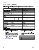
Performance Charts Performance Charts Use these charts to help identify the proportioner that will work most efficiently with each mix chamber. Flow rates are based on a material viscosity of 60 cps. NOTICE To prevent system damage, do not pressurize the system above the line for the gun tip size being used. Proportioners For Foam 2000 (138) AR4242 (01) AR5252 (02) 1500 (103) PRESSURE psi (bar) AR6060 (03) 1000 (69) AR7070 (04) E-30 500 (34) 0 333024E 5 (2.3) 10 (4.5) 15 (6.8) 20 (9.
Performance Charts Proportioners For Coatings Table 1 Fusion Air Purge, Round Pattern 3500 (241) 3000 (207) 2500 PRESSURE psi (bar) E-XP2 AR2020 (000) (172) AR2929 (00) 2000 (138) 1500 (103) AR4242 (01) 1000 (69) 500 (34) 0 0.5 1.0 (1.9) 1.5 (3.8) FLOW gal./min (l/min) 2.0 (5.7) (7.6) Table 2 Fusion Air Purge, Flat Pattern 3500 (241, 24.1) 3000 (207, 20.7) AF2929 (FTXX38 TIP) 2500 (174, 17.4) PRESSURE psi (bar) AF2020 (FTXX24 TIP) 2000 (138, 13.
Performance Charts Table 3 Fusion Mechanical Purge, Round Pattern 3500 (241, 24.1) E-XP2 3000 (207, 20.7) XR2323 (RTM040) 2500 (174, 17.4) PRESSURE psi (bar) XR2929 (RTM040) 2000 (138, 13.8) MR3535 (RTM040) 1500 (103, 10.3) XR3535 (RTM055) 1000 (69, 6.9) MR4747 (RTM055) XR4747 (RTM055) 500 (35, 3.5) 0 0.5 (1.9) 1 1.5 (3.8) 2.0 (5.7) FLOW gal./min (l/min) (7.6) Table 4 Fusion Mechanical Purge, Flat Pattern 3500 (241, 24.1) XF2323 (FTM424) XF1313 (FTM424) 3000 (207, 20.
Technical Specifications Technical Specifications Reactor 2 E-30 and E-XP2 Proportioning System Maximum Fluid Working Pressure E-30 E-XP2 Maximum Fluid Temperature E-30 E-XP2 Maximum Flow Rate E-30 E-XP2 Maximum Heated Hose Length Length U.S. Metric 2000 psi 3500 psi 14 MPa, 140 bar 24.1 MPa, 241 bar 190°F 190°F 88°C 88°C 30 lb/min 2 gpm 13.5 kg/min 7.6 lpm 310 ft 94 m 0.0272 gal. 0.0203 gal. 0.1034 liter 0.
Technical Specifications Sound Pressure Sound Pressure measured per ISO-9614–2. E-30 87.3 dBA E-XP2 79.6 dBA Sound Power E-30 93.7 dBA E-XP2 86.6 dBA Measured from 3.1 ft (1 m), at 1000 psi (7 MPa, 70 bar), 3 gpm (11.4 lpm) Measured from 3.1 ft (1 m), at 3000 psi (21 MPa, 207 bar), 1 gpm (3.8 lpm) Measured from 3.1 ft (1 m), at 1000 psi (7 MPa, 70 bar), 3 gpm (11.4 lpm) Measured from 3.1 ft (1 m), at 3000 psi (21 MPa, 207 bar), 1 gpm (3.
Notes Notes 98 333024E
Graco Extended Warranty for Reactor® 2 Components Graco warrants all equipment referenced in this document which is manufactured by Graco and bearing its name to be free from defects in material and workmanship on the date of sale to the original purchaser for use. With the exception of any special, extended, or limited warranty published by Graco, Graco will, for a period of twelve months from the date of sale, repair or replace any part of the equipment determined by Graco to be defective.
Graco Information For the latest information about Graco products, visit www.graco.com. To place an order, contact your Graco Distributor or call to identify the nearest distributor. Phone: 612-623-6921 or Toll Free: 1-800-328-0211 Fax: 612-378-3505 All written and visual data contained in this document reflects the latest product information available at the time of publication. Graco reserves the right to make changes at any time without notice. For patent information, see www.graco.com/patents.