INSTRUCTIONS SDMM8 Manual Meter and SDMP8 Preset Meter 333492B EN For metered dispense of petroleum-based lubricants, oils and 50:50 antifreeze/water mix fluids only. For professional use only. Maximum Working Pressure: 1500 psi (10 MPa, 103 bar) List of Models page 2 Important Safety Instructions Read all warnings and instructions in this manual. Save these instructions.
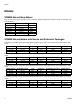
Models Models SDMM8 Manual Bare Meters Bare manual meters do not include a nozzle or extension. Model packages that include a nozzle and extension are provided below.
Models The following packages include Bare Meter Model 24U957 and the nozzle and extension kits indicated in the table below. Model Number Model Description 24V044 24V047 24V050 4/16 Liter 4/16 Liter 4/16 Liter Inlet Extension Nozzle/Extension Kit Nozzle Parts† BSPT BSPT BSPT Flex Rigid Gear Lube 24V475 255852 255854 255459 255459 255470 The following packages include Bare Meter Model 24U958 and the nozzle and extension kits indicated in the table below.
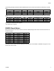
Models SDMP8 Preset Meters with Nozzle and Extension Packages The following packages include Bare Meter Model 24U947 and the nozzle and extension kits indicated in the table below. Model Number Model Description 24V052 60 Quart Inlet Extension Nozzle/Extension Kit Nozzle Parts† NPT Rigid 24W641 255459 The following packages include Bare Meter Model 24U948 and the nozzle and extension kits indicated in the table below.
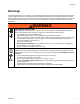
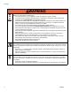
Warnings Warnings The following warnings are for the setup, use, grounding, maintenance, and repair of this equipment. The exclamation point symbol alerts you to a general warning and the hazard symbols refer to procedure-specific risks. When these symbols appear in the body of this manual or on warning labels, refer back to these Warnings. Product-specific hazard symbols and warnings not covered in this section may appear throughout the body of this manual where applicable.
Warnings WARNING WARNING EQUIPMENT MISUSE HAZARD Misuse can cause death or serious injury. • Do not operate the unit when fatigued or under the influence of drugs or alcohol. • Do not exceed the maximum working pressure or temperature rating of the lowest rated system component. See Technical Data in all equipment manuals. • Use fluids and solvents that are compatible with equipment wetted parts. See Technical Data in all equipment manuals. Read fluid and solvent manufacturer’s warnings.
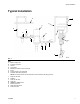
Typical Installation Typical Installation A L K R F B D C G P E M J H S N FIG.
Installation Installation NOTE: The letters used in the following instructions refer to Typical Installation on page 7. Grounding Pressure Relief Procedure Follow the Pressure Relief Procedure whenever you see this symbol. This equipment stays pressurized until pressure is manually relieved.
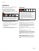
Installation Component Identification 101 41 102 37 12 1 FIG.
Installation Pre-Installation Procedure 4. Slowly open the fluid shut off valve (J). NOTE: The letters used in the following instructions refer to Typical Installation on page 7 and the Component Identification on page 9. Numbers used in the following instructions refer to the Parts List on pages 19 21. 5. If you have multiple dispense positions, first flush the dispense position farthest from the pump and work your way toward the pump. Slowly open the fluid shut-off valve (L) at the dispense position.
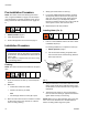
Installation d. Wrench tighten extension nut (102a). 4. Install extension (102) to meter: a. Loosen extension nut (102a) (FIG. 4) until it is completely off tube threads. 102 5. Install nozzle (101): NOTE: Do not use PTFE tape or thread sealant on threads of nozzle (101). This could cause the fitting to leak. a. Thread nozzle (101) onto extension (102) as shown in FIG. 7. . 102 102a FIG. 4 101 NOTE: Do not use PTFE tape or thread sealant on threads of extension (102).
Operation Operation The totalizer keeps a running total of the amounts dispensed. NOTE: The letters used in the following instructions refer to Typical Installation on page 7 and the Component Identification on page 9. Numbers used in the following instructions refer to the Parts List on pages 19 21. 1. Turn meter pointer (41) counter-clockwise to select the desired volume. 1. Open fluid shut off valves (J and L). 2. Start pump (F) to pressurize system. 3.
Troubleshooting Troubleshooting Relieve pressure, page 8, before you check or repair the meter. Be sure all other valves, controls and pump are operating properly. Problem Cause Strainer (3a) is clogged. Slow or no fluid flow. Meter leaks from twist lock nozzle. • It is important to distinguish between the two causes of this problem. A new nozzle will NOT correct a fluid leak caused by a faulty valve. 1. Relieve pressure, page 8. 2. Remove meter from hose. 3. Clean or replace strainer (3a).
Service Service Cleaning / Repairing the Fluid Section 5. Remove seal (18) and piston assembly (19). If the piston assembly sticks, lightly tap the housing against a flat surface to loosen it (FIG. 12). NOTE: Do not disassemble the fluid and counting sections simultaneously. Confirm the fluid section is fully assembled before removing the counting section. 19 18 1. Relieve pressure, page 8. 2. Close fluid shut off valve (L). 3. Remove nozzle (101) and extension (102). FIG. 12 6.
Service SDMM8 Manual Meter Counter Section Repair 4. Use a hex wrench to remove the plug setscrew. Remove the plug (50), remove the pin (51), spring (53), and the lower pointer (52) (FIG. 16). Disassembly 50 NOTE: Do not disassemble the fluid and counting sections simultaneously. Confirm the fluid section is fully assembled before removing the counting section. 1. Relieve pressure, page 8. 2. Remove the cover (44), small retaining ring (43), pointer pin (41) and pointer spring (42) (FIG. 14).
Service 7. Remove the entire counter assembly (31) (FIG. 19). 3. Install the face plate panel (37) and large retaining clip (38) (FIG. 22). 38 31 37 FIG. 19 FIG. 22 Reassembly 4. Install the lower pointer (52), spring (53), pin (51) and plug (50) as shown in FIG. 23. Use a hex wrench to tighten the plug setscrew. 1. Install counter assembly (31). 50 31 51 52 53 FIG. 23 5. Install the needle pointer (41), springs (39) and pins (40) as shown in FIG. 24. FIG. 20 2.
Service 6. Install small retaining ring (43), pointer pin (41) and pointer spring (42). Install the cover (44). (FIG. 25). 43 3. Remove the needle pointer (41), springs (39) and pins (40) (FIG. 27). 41 44 42 39/40 41 FIG. 25 FIG. 27 SDMP8 Preset Meter Counter Section Repair 4. Remove the large retaining clip (38) and then the face plate panel (37) (FIG. 28). 38 Disassembly 37 NOTE: Do not disassemble the fluid and counting sections simultaneously.
Service 6. Remove the entire counter assembly (31) (FIG. 30). 3. Install face plate panel (37) and large retaining clip (38) (FIG. 33). 31 38 37 FIG. 30 Reassembly FIG. 33 1. Install counter assembly (31) (FIG. 31). 4. Install the needle pointer (41), springs (39) and pins (40) as shown in FIG. 34. 31 41 39/40 FIG. 34 FIG. 31 2. Install the gears (32, 34). Use a 2 mm hex wrench to tighten gear set screw (33). (FIG. 32). 5. Install small retaining ring (43) and cover (44) (FIG. 35).
SDMM8 Manual Meter Parts SDMM8 Manual Meter Parts Models 24U959, 24U960, 24U961, 24U956, 24U957, 24U958 Ref A Ref B 28 33 44 41 43 See Ref B 19g 35 19f 42 50 39 19d 34 51 36 40 39 19c 40 38 19b 52 39 40 37 19a 11 1 1 3b 3a 5 6 7 8 9 10 2 31 14 29 13 17 3 14 15 2 16 19 See Ref A 18 46 12 1 Torque to 7-10 ft lbs (9-13 N.m) 33 32 2 16 15 47 49 45 48 2 Torque to 15-25 in. lbs (1.7-2.8 N.m) 3 Torque to 11-14 ft. lbs (14.9-18.9 N.
SDMM8 Manual Meter Parts SDMM8 Manual Meter Parts Models 24U959, 24U960, 24U961, 24U956, 24U957, 24U958 Ref Part No. 1 SWIVEL Qty 1 Ref Part No.
SDMP8 Preset Meter Parts SDMP8 Preset Meter Parts Models 24U947, 24U948, 24U949, 24U950, 24U951, 24U952, 24U953, 24U954, 24U955 Ref A 30 Ref B 19g 44 19f See Ref B 43b 19a 41 19c 34 42 40 39 19b 51 39 11 3b 3a 5 6 7 38 40 50 46 19d 45 8 9 10 11 35 49 47 37 43a 32 33 31 48 2 16 15 19 See Ref A 18 2 17 3 52 1 Torque to 7-10 ft lbs (9-13 N.m) 12 14 13 14 28 15 16 2 2 Torque to 15-25 in. lbs (1.7-2.8 N.m) 3 Torque to 11-14 ft. lbs (14.9-18.9 N.
SDMP8 Preset Meter Parts SDMP8 Preset Meter Parts Models 24U947, 24U948, 24U949, 24U950, 24U951, 24U952, 24U953, 24U954, 24U955 Ref Part No. Description Qty Part No.
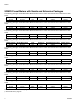
SDMP8 Preset Meter Parts Ref 36 Part No. Description 16X587 16Y999 16X588 17A029 37 Qty GEAR, twin 11-44 teeth (not shown) Models 24U947, 24U948, 24U949, 24U953, 24U954, 24U955 1 GEAR, twin 24-44 teeth (not shown) Models 24U950, 24U951, 24U952 1 GEAR. twins, 14-32, (not shown) Models 24U950, 24U951, 24U952 1 GEAR, 11-42 teeth (not shown) Models 24U950, 24U951, 24U952 1 DIAL 1 Ref Part No.
Nozzle (101) and Extension (102) Kits Nozzle (101) and Extension (102) Kits Kit No.
Nozzle (101) Parts Nozzle (101) Parts Part No.
Technical Data Technical Data Manual and Preset Meter Flow rate* Maximum working pressure Weight Manual Meter Preset Meter Dimensions (without extension) (see page 27) Length Width Height Manual Meter Height Preset Meter Maximum Totalizer Digits Inlet US 0.26 to 8 gpm 1500 psi Metric 1 to 30 lpm 10 MPa, 103.4 bar 3.42 lbs 3.50 lbs 1.55 kg 1.58 kg 11.4 inches 3.94 inches 4.85 inches 6.33 inches 28.9 cm 10 cm 12.3 cm 16.
Technical Data Dimensions Manual Meter Preset Meter FIG. 36 FIG.
Graco Extended Meter Warranty Graco warrants all equipment referenced in this document which is manufactured by Graco and bearing its name to be free from defects in material and workmanship on the date of sale to the original purchaser for use. Graco will, for a period of five (5) years from the date of sale, repair or replace any non-wear parts of the equipment determined by Graco to be defective.