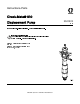
Instructions-Parts Check-Mate® 800 Displacement Pump For use with hot-melt applications. For professional use only. Important Safety Instructions Read all warnings and instructions in this manual and in related system manuals. Save these instructions. Maximum Operating Temperature 400°F (204 °C) Maximum Fluid Working Pressure 5850 psi (40 MPa, 403 bar) PROVEN QUALITY. LEADING TECHNOLOGY.
Contents Models............................................................... Related Manuals ................................................ Warnings ........................................................... Component Identification..................................... Installation.......................................................... Grounding ................................................... Connect to a Graco Air Motor ....................... Pressure Relief Procedure ..........................
Warnings Warnings The following warnings are for the setup, use, grounding, maintenance, and repair of this equipment. The exclamation point symbol alerts you to a general warning and the hazard symbols refer to procedure-specific risks. When these symbols appear in the body of this manual or on warning labels, refer back to these Warnings. Product-specific hazard symbols and warnings not covered in this section may appear throughout the body of this manual where applicable.
Warnings WARNING FIRE AND EXPLOSION HAZARD Flammable fumes, such as solvent and paint fumes, in can ignite or explode. To help prevent fire and explosion: • Use equipment only in well ventilated area. • Eliminate all ignition sources; such as pilot lights, cigarettes, portable electric lamps, and plastic drop cloths (potential static arc). • Keep work area free of debris, including solvent, rags and gasoline.
Warnings WARNING TOXIC FLUID OR FUMES HAZARD Toxic fluids or fumes can cause serious injury or death if splashed in the eyes or on skin, inhaled, or swallowed. • Read MSDSs to know the specific hazards of the fluids you are using. • Store hazardous fluid in approved containers, and dispose of it according to applicable guidelines.
Component Identification Component Identification 6 Key: A B C D E F G H J K Displacement Pump Wetcup Throat Packing Outlet Housing Fluid Outlet Bleed Valve Cylinder Intake Housing Intake Cylinder Priming Piston 334127A
Installation Installation Grounding The equipment must be grounded to reduce the risk of static sparking. Static sparking can cause fumes to ignite or explode. Grounding provides an escape wire for the electric current. Pump: the pump is grounded with a wire connecting the pump from the control enclosure. Locate the small hole (W) in the pump outlet housing. Attach the ground wire (Y) to the pump outlet housing using the ground screw (X) supplied with your system. Tighten the ground screw securely.
Pressure Relief Procedure Pressure Relief Procedure Follow the Pressure Relief Procedure whenever you see this symbol. This equipment stays pressurized until pressure is manually relieved. To help prevent serious injury from pressurized fluid, such as skin injection, splashing fluid and moving parts, follow the Pressure Relief Procedure when you stop spraying and before cleaning, checking, or servicing equipment. Heated fluid can cause severe burns and can cause equipment surfaces to become very hot.
Repair Repair Required Tools • • • • • • • • • • • • • • Torque wrench Bench vise, with soft jaws Rubber mallet Hammer O-ring pick 13 mm (1/2 in.) dia. brass rod Set of socket wrenches Set of adjustable wrenches Pipe wrench Screwdriver Heat gun Gloves Thread lubricant Thread sealant Note The priming piston can be serviced without disconnecting the displacement pump from the motor. see Replace Priming Piston, page 11. 1. Flush the pump, if possible.
Repair Replace Throat Packings 6. If necessary, use an arbor press to install o-ring (27) in packing housing (25). 7. Screw the packing nut (2) and packing housing (25) into the outlet housing (3). Torque to 150 ± 30 ft-lb (203 ± 41 N•m). Note The throat packings are available as a preassembled kit. Pump Part No. Throat Seal Repair Kit 24W152 24W153 24W150 24W151 24V752 24V753 24V752 24V753 1. Relieve the pressure. See Pressure Relief Procedure, page 8 . 2. See Fig. 2.
Repair Replace Priming Piston Pump Part No. Repair Kit 24W152 24W153 24W150 24W151 237910 237910 237909 237909 1. Stop the pump on the downstroke, with the flats of the priming piston rod (17) exposed below the intake cylinder (18). It is not necessary to disconnect the displacement pump from the motor, but you may have to disconnect it from the heated platen. Figure 3 Priming Piston 334127A 2. Relieve the pressure. See Pressure Relief Procedure, page 8 . 3.
Repair Replace Intake Valve Note The intake valve (V) is available as a preassembled, pre–lubricated kit. The kit includes the valve and all seals and packings, and also includes the intake valve seat (15) and seal (16). See Fig. 5. Pump Part No. Repair Kit 24W152 24W153 24W150 24W151 253546 237907 253546 237907 1. Relieve the pressure. See Pressure Relief Procedure, page 8 . 2. Disconnect the displacement pump. See system manual for instructions. 3.
Repair 6. Pull the intake seat (15) and seal (16) out the bottom of the intake housing (13). Note If the seat (15) is difficult to remove, insert a brass rod through the top of the housing (13) and drive the seat out with a hammer. Figure 5 7. Firmly tap the piston rod with a rubber mallet and until the valve assembly comes free. Take care not to drop the valve assembly (V) as it comes free. 8. To repair the piston, cylinder, seals, and rods, see Repair Piston, page 14. 9.
Repair Repair Piston 4. Remove the seal (6) from the bottom of the cylinder (8). See Fig. 7. Shine a light into the cylinder to examine the inside surface for scoring or damage. Only if the cylinder is damaged, or there is evidence of leaking around the top cylinder seal (6), unscrew the cylinder from the Note The piston valve is available as a preassembled, pre–lubricated kit. The kit includes the piston seat/guide assembly (P, items 6, 9, 10, 11, and 12). Order Part No. 237906. 1.
Repair 6. Place the piston (9) flats in a vise and unscrew the rod (17). 7. Place the preassembled piston seat/guide assembly (P, items 10, 11, and 12) onto the piston (9) so the 45 beveled seating surfaces match. 8. Place the flats of the displacement rod (1) in a vise. Screw the piston (9) onto the displacement rod (1) hand tight, then torque to 250–265 ft-lb (339–359 N•m). Figure 10 9. Using an adjustable wrench on the flats of the priming piston rod (17), screw the rod into the piston (9).
Parts Parts 5 Gallon (20 Liter) Pumps 24W152, Pump with Carbon Filled Seals 24W153, Pump with Glass Filled Seals 1 2 3 4 5 16 Torque to 25 +/- 2 ft-lbs (25 +/- 2.7 N•m) Torque to 390 +/- 45 ft-lbs (528 +/- 61 N•m) Torque to 150 +/- 30 ft-lbs (203 +/- 40 N•m) Torque to 60 +/- 3 ft-lbs (81 +/- 4 N•m) Torque to 97 +/- 5 ft.-lbs (131 +/- 7 N•m) Torque to 225 +/- 10 ft-lbs (131 +/- 13 N•m) 7 Torque to 255 +/- 16 ft-lbs (345 +/- 21 N•m) 8 Torque to 75 +/- 4 ft-lbs (101 +/- 5 N•m) 9 Apply lubricant.
Parts 24W152, Pump with Carbon Filled Seals 24W153, Pump with Glass Filled Seals Ref.
Parts 55 Gallon (200 Liter) Pumps 24W150, Pump with Carbon Filled Seals 24W151, Pump with Glass Filled Seals 1 2 3 4 5 18 Torque to 25 +/- 2 ft-lbs (25 +/- 2.7 N•m) Torque to 390 +/- 45 ft-lbs (528 +/- 61 N•m) Torque to 150 +/- 30 ft-lbs (203 +/- 40 N•m) Torque to 60 +/- 3 ft-lbs (81 +/- 4 N•m) Torque to 97 +/- 5 ft.-lbs (131 +/- 7 N•m) Torque to 225 +/- 10 ft-lbs (131 +/- 13 N•m) 7 Torque to 255 +/- 16 ft-lbs (345 +/- 21 N•m) 8 Torque to 75 +/- 4 ft-lbs (101 +/- 5 N•m) 9 Apply lubricant.
Parts 24W150, Pump with Carbon Filled Seals 24W151, Pump with Glass Filled Seals Ref 1 Part Description 16Y958 ROD, displacement, chromex,11cm 2 237799 NUT, packing 3 190598 HOUSING, outlet 4 237908 BLEEDER VALVE KIT 6* 113040 PACKING, o-ring 7* 15M521 BEARING, piston guide cm200 8 189437 CYLINDER, pump 9* 189439 SEAT, piston, sst 10* 15M520 GUIDE, piston, 200 11* 113355 BEARING, piston 12* 189441 SEAT, piston 13 190597 HOUSING, valve 14 189514 VALVE, intake 15 189446 SEAT, valve 16 113041 PACKING, o-r
Technical Specifications Technical Specifications Check-Mate 800 Displacement Pump US Maximum fluid working pressure Displacement pump effective area Maximum pump operating temperature Fluid outlet size Wetted parts 5850 psi 1.24 in.2 400°F Metric 40 MPa, 403 bar 8 cm2 200°C 1 in.
Notes Notes 334127A 21
Graco Standard Warranty Graco warrants all equipment referenced in this document which is manufactured by Graco and bearing its name to be free from defects in material and workmanship on the date of sale to the original purchaser for use. With the exception of any special, extended, or limited warranty published by Graco, Graco will, for a period of twelve months from the date of sale, repair or replace any part of the equipment determined by Graco to be defective.