Instructions ™ PR70e Compact Benchtop Meter, Mix and Dispense System 334135B EN Use for accurate metering, mixing and dispensing of two-component sealants and adhesives in fixed ratios. Not for use with isocyanate catalyzed materials. For professional use only. Not approved for use in explosive atmospheres or hazardous locations. Refer to Models, page 3, for maximum working pressures. Important Safety Instructions Read all warnings and instructions in this manual. Save these instructions.
Contents Models . . . . . . . . . . . . . . . . . . . . . . . . . . . . . . . . . . . 3 Related Manuals . . . . . . . . . . . . . . . . . . . . . . . . . . . 3 Warnings . . . . . . . . . . . . . . . . . . . . . . . . . . . . . . . . . 4 Component Identification . . . . . . . . . . . . . . . . . . . . 6 Machine . . . . . . . . . . . . . . . . . . . . . . . . . . . . . . . 6 Local Control Module (LCM) . . . . . . . . . . . . . . . . 7 LCM Screen Navigation . . . . . . . . . . . . . . . . . . .
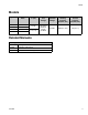
Models Models System MD2 Valve Ratio 24S054 1:1 24S055 10:1 24S056 1:1 24S057 10:1 Air Motor in. (cm) Required Line Voltage Machine Operation Voltage Maximum Working Pressure psi (MPa, bar) Maximum Air Inlet Pressure psi (MPa, bar) 3 (7.6) 100-240 V 50/60 Hz, 1 phase 50 Watts 24 VDC 3000 (21, 207) 100 (0.7, 7) 4.5 (11.
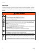
Warnings Warnings The following warnings are for the setup, use, grounding, maintenance, and repair of this equipment. The exclamation point symbol alerts you to a general warning and the hazard symbols refer to procedure-specific risks. When these symbols appear in the body of this manual or on warning labels, refer back to these Warnings. Product-specific hazard symbols and warnings not covered in this section may appear throughout the body of this manual where applicable.
Warnings WARNING WARNING FIRE AND EXPLOSION HAZARD Flammable fumes, such as solvent and paint fumes, in work area can ignite or explode. To help prevent fire and explosion: • Use equipment only in well ventilated area. • Eliminate all ignition sources; such as pilot lights, cigarettes, portable electric lamps, and plastic drop cloths (potential static arc). • Keep work area free of debris, including solvent, rags and gasoline.
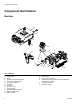
Component Identification Component Identification Machine L M A K J D F E R G N T H S B C P FIG.
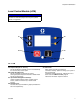
Component Identification Local Control Module (LCM) NOTICE To prevent damage to soft key buttons, do not press the buttons with sharp object such as pens, plastic cards, or fingernails. AC AD AB AA AE FIG. 2: LCM Key: AA Dispense Request or “Go” key This key will dispense material and can not be disabled by the user as a setup screen option. AB System Shut-Down Key This key will disable the machine (all outputs de-energized) and will place the machine in disable mode. This key is always active.
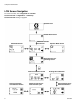
Component Identification LCM Screen Navigation For screen overview, refer to Appendix B - LCM Run Screen Overview and Appendix C - LCM Setup Screen Overview starting on page 62.
Component Identification 334135B 9
Recommended Parts Recommended Parts Dispense Valve Standard Dispense Valves, 255179 and 255181 See MD2 manual for parts information.
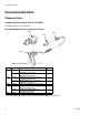
Recommended Parts Lever Actuated MD2 Valves, LC0121 and LC0123 1101a 1101b 1103 1102 Assembly LC0121 Shown ti12441a Ref 1101 Part LC0005 LC0007 1101a 1101b 255249 255181† 255179† 1102 121198 123660 1103 120953 Description VALVE, assembly, 1:1, lever, electric (assembly LC0121 only) VALVE, assembly, 10:1, lever, electric (assembly LC0123 only) LEVER, 2K dispense valve VALVE, dispense, 10:1, soft seats (assembly LC0123 only) VALVE, dispense, 1:1, soft seats (assembly LC0121 only) CORD, euro, mal
Recommended Parts Mixers 1301 1303 1302 Assembly LC0061 Shown ti12442a 12 334135B
Recommended Parts Reference Number and Description 1301 1302 1303 Mixer Package Description Mixer Part No. (Quantity) Shroud Part No. (Quantity 1) Sleeve Part No. (Quantity 1) LC0063 3/16 in. x 32 60/0206/50 (10) 94/0884-1/98 --- LC0077 3/16 in. x 32 60/0206/50 (50) --- --- LC0084 3/16 in. x 32 60/0206/50 (250) --- --- LC0061 3/16 in. x 32 Luer Lock 16D012 (10) 16P448 60/0313/97 LC0082 3/16 in. x 32 Luer Lock 16D012 (50) --- --- LC0089 3/16 in.
Recommended Parts Applicator Mounting Mast Mount, Controls and MD2 Applicator, LC0292 Mast Mount, Controls only, LC0293 812 803 811 805 802 804 804 802 814 803 801 806 807 811 Quantity Ref 801 802 803 804 805 806 807 809* 810* 811 812 814 * 14 Part 16P082 16P409 16P550 121194 15K832 120913 15M658 121046 94/0705-1/96 126510 121273 121013 Description BASE, arm, mounting BLOCK, mounting, front BLOCK, mounting, rear SCREW ARM, mounting, HMI SCREW CLAMP TUBE, 1/4 x 1/4 twin, polyurethane FITTING, e
Recommended Parts Air Filter and Ball Valve, 24R707 704 703 701 705 702 Ref 701 702 703 704 705 Part --157350 106148 155665 --- Description VALVE, vented 2 way ADAPTER FILTER, air, 3/8 NPT UNION, adapter NIPPLE, pipe Quantity 1 1 1 1 1 High Temperature Grease, 115982 Footswitch, 255244 334135B 15
Recommended Parts Tanks 1 1/2 in.
Recommended Parts Ref 1001 1002 1003 1004 1005 1006 1007 1008 1009 1010 1011 1014 1015 1018 1019 1020 1023 1024 1025 1026* * Part 95/0223/00 120901 120902 120904 120905 120906 120907 120908 120909 120911 120913 255280 121013 ----15K840 --15M226 15K842 120915 15M237 Description O-RING O-RING SCREW, M5x40mm SCREW, M5x18mm NUT, hex, lock M5 NUT, hex, lock M8 x 1.
Recommended Parts Hose Packages Unheated, Non-Recirculating Hose 1404 1403 1401 1402 Assembly LC0801 Shown ti12446a 1 Apply thread sealant tape to male npt threads before assembly. Reference Number and Description Hose Package Description LC0801 3/16 in. x 30 in. LC0802 3/16 in. x 120 in. LC0803 3/16 in. x 180 in. LC0804 1/4 in. x 30 in. LC0805 1/4 in. x 120 in. LC0806 1/4 in. x 180 in. LC0807 3/8 in. x 30 in. LC0808 3/8 in. x 120 in. LC0809 3/8 in. x 180 in. LC0400* 3/8 in. x 30 in. LC0401* 3/8 in.
Recommended Parts 334135B 19
Recommended Parts Piston Package 606 1 601 606 605 603 ti12438a 602 604 1 Arrow on cylinder must point to the o-ring (606) on the right.
Recommended Parts UHMW Piston, Stainless Steel Metering Tube Assemblies Reference Number and Description Piston Package LC2160 LC2180 LC2200 LC2220 LC2240 LC2260 LC2280 LC2300 LC2320 LC2360 LC2400 LC2440 LC2480 LC2520 LC2560 LC2600 LC2640 LC2720 LC2800 LC2880 LC2960 Quantity 601 602 Tube, pump LCC160 LCC180 LCC200 LCC220 LCC240 LCC260 LCC280 LCC300 LCC320 LCC360 LCC400 LCC440 LCC480 LCC520 LCC560 LCC600 LCC640 LCC720 LCC800 LCC880 LCC960 1 UHMW Piston LCA160 LCA180 LCA200 LCA220 LCA240 LCA260 LCA280 LC
Pump Tube Combination Information Pump Tube Combination Information Pump Tube Combination Information Ratio Large Piston Small Piston Minimum (X:1) (mm) (mm) Shot Size (cc) 1 960 960 12.4 1 640 640 8.3 1 480 480 6.2 1 320 320 4.1 1 240 240 3.1 1 160 160 2.1 1 120 120 1.6 1 80 80 1.0 1.50 240 160 2.6 1.50 960 640 10.4 1.50 480 320 5.2 1.50 120 80 1.3 2 960 480 9.3 2 640 320 6.2 2 480 240 4.7 2 320 160 3.1 2 240 120 2.3 2 160 80 1.6 3 960 320 8.3 3 480 160 4.1 3 240 80 2.1 4 960 240 7.8 4 640 160 5.
Installation Installation Machine Installation Grounding The equipment must be grounded to reduce the risk of static sparking and electric shock. Electric or static sparking can cause fumes to ignite or explode. Improper grounding can cause electric shock. Grounding provides an escape wire for the electric current. General Grounding Guidelines Pump: use ground wire and clamp (P). Refer to page 6 for component identification. Connect ground wire and clamp to a true earth ground.
Installation Install Pump Tubes See Piston Package on page 20 and Nylon and UHMW Piston Replacement Kits on page 65 for kit numbers. 7. Install the pump cap onto the assembly using the four bolts. Finger tighten the bolts, then torque the bolts to 350 in-lb (40 N•m) in a crisscross pattern. NOTE: Ensure that high volume and low volume pump tubes are installed on the correct side of the machine. 1 3 4 2 High Volume Install the Chemical Hoses. Low Volume 5.
Installation Connect the Footswitch or External Device. Electrical Requirements 11. Connect AC power (100-240V, 50/60 Hz, single-phase) to the power supply provided. Connect the power supply to the machine as shown. Connect Pressurized Air Input 8. Install an air inlet bleeding ball valve and air filter kit (not provided with unit, but available as kit 24R707) at the 1/4 NPT female air inlet. NOTICE The system must have a bleed-type ball valve that bleeds pressure downstream when closed.
Setup Setup Before setting up the machine, the user needs to be familiar with the LCM screens. Refer to Appendix A LCM Icon Overview and Appendix B - LCM Run Screen Overview, starting on page 60. Perform Startup, page 33, to access the LCM screens. 3. Place a waste container under the dispense valve to capture any dispensed material. 4. Ensure the system air pressure is on by opening the vented ball valve and the system air pressure regulator shows air pressure in the system.
Setup 10. Press the Enter button ( ) to accept the new value or press the Abort/Cancel button ( ) to 16. Press the Enter button ( ) to accept the value or press the Abort/Cancel button ( ) to keep the previous value. keep the previous value. Engaged Piston Position Prepare Machine for Operation 11. Close the vented ball valve to eliminate the air pressure to the system. 17. High light the Retract Piston button ( ). 18. Press the Dispense Request button ( ). 12.
Setup Prime the Dispense Head 9. Select a large size shot. 10. Hold a waste container at the end of the dispense head and press the Dispense Request button ( NOTICE If the dispense head is not primed, chemical crossover may occur resulting in cured material in the dispense head, hoses, and/or pumps. 1. Remove static mixer from the dispense head if installed. 2. Turn snuff-back adjustment knob fully clockwise. This will prevent the dispense valve from closing between priming shots. ) or the footswitch.
Setup Phasing Adjustment Adjust Dispense Quantity 6. Press the Phasing shot button ( phasing mode. 7. Press the Dispense Request button ( ) to enter ) or the footswitch to dispense a very small amount of material. 8. Adjust the displayed percentage if more than a couple drops of either material was dispensed or if no material was dispensed from both sides. • If too much material was dispensed, decrease the phasing percentage.
Setup Adjust Phasing b. Hold the phase adjustment screw (003) stationary with a 13 mm wrench. c. Use a 7 mm wrench to turn the piston shaft (001) counterclockwise 1/4 turn or less to move the A piston forward. 003 002 001 NOTE: It is highly recommended that all of the phasing adjustment be done to one side or the other; not both. NOTE: Ensure the piston shaft and phase adjustment screw do not rotate while tightening the locking nut (002) in the following step.
Setup Adjust Dispense Valve Snuff Back At the end of a shot, a small amount of material is drawn back into the static mixer to prevent extra material from being dispensed. If too much snuff back occurs, air will enter the static mixer and can travel up into the dispense valve. If too little snuff back occurs, the materials may drip out of the static mixer and affect dispense quantity.
Setup Adjust Open Dispense Valve (ODV) Timing If a high positive number is entered for ODV timing, such as 6.0 mm, the dispense valve may not open resulting in the fluid stalling against the dispense valve. The fluid in the hose lines will remain under pressure until the piston is manually retracted using the Manual screen, see Operator Mode Screen. When a shot is performed, the dispense valve needs to open at a precise time for material to be dispensed properly.
Operation Operation Startup Pressure Relief Procedure Follow the Pressure Relief Procedure whenever you see this symbol. 1. Locate the power switch at rear of machine and turn the power on. The display module will automatically turn on and begin to load. 2. Open the vented ball valve (not provided). 3. If the machine is in Disabled Mode, press the Power On button ( ) to exit Disabled mode and to select a new operating mode.
Operation Shutdown If the machine is to remain idle for an extended period of time, perform the following steps. 1. If installed, remove static mixer from the end of the dispense valve. 2. Place a container below the dispense valve and activate a small shot to flush mixed material out of the valve. 3. Relieve pressure. See Pressure Relief Procedure, page 33. 4. With a clean rag and cotton swabs, clean the end of the dispense valve. 5. Install the nightcap on the dispense valve.
Maintenance Maintenance Schedule Action Schedule Procedure Check Water/Air Separator (Not provided) Daily before use 1. Check water/air separator for water. 2. Open valve at base of water/air separator to purge water. Check Desiccant Dryer (only installed if chemical is moisture sensitive) Daily before use 1. Check the color of the desiccant 2. Replace as required. Check Tanks Daily before use 1. Check material levels and refill as necessary. 2.
Maintenance Install Upgrade Token This procedure applies to the Local Control Module (LCM). 1. Disconnect power to the module. 2. Remove token access panel. FIG. 10: Remove Access Panel 3. Press firmly the token into the slot. NOTE: There is no preferred orientation of the token. 4. Restore power to the module. The red LED will flash rapidly to signal that software is loading. When the red LED stops flashing, the software is done loading. 5. Disconnect the power to the module. 6. Remove the token. 7.
Troubleshooting Troubleshooting Before starting any troubleshooting procedures, perform the following procedure. 3. Allow the machine to cool if the machine has a heat control option. 1. Relieve pressure. See Pressure Relief Procedure, page 33. Try the recommended solutions in the order given for each problem to avoid unnecessary repairs. Verify all circuit breakers, switches, and controls are properly set and wiring is correct. 2. Disconnect AC power from the machine.
Troubleshooting Problem Machine dispensing off ratio Pumps drawing material back from valve hose 38 Cause Solution One tank is empty Check tank levels. Add material if necessary. Tank ball valve closed Open tank ball valve. Prime machine. Machine out of phase Re-phase machine. Check valve malfunction Remove check valve; clean or replace as necessary. Piston worn or broken Replace piston. Check valve stuck open Remove check valve, clean or replace as necessary.
Troubleshooting LCM Error Codes If an error condition exists, the front Panel LED will blink the number of times corresponding to the error code number, pause, then repeat. After the user acknowledges the generated error screen, the error number will appear on the bottom left-hand side of the main run screen, and the described blink sequence will continue. If more than one error is present, all will be presented, separated by commas.
Repair Repair HydraCheck Kit Installation, 24W336 Be sure that system pressure is relieved and disabled before proceeding. FIG. 11: HydraCheck Installation - Fixed Ratio Base NOTE: The HydraCheck kit is intended to be used with low viscosity materials to minimize splashing. It is not intended to be used as a timer or flow control device. Prepare Machine for Kit Installation Install HydraCheck Shock 6.
Repair Install Adjustment Screw/Cap 9. Loosely install hex nut and adjustment cap onto the air cylinder shaft. Adjust the Adjustment Screw/Cap 10. Push the drive block forward until resistance is felt when it engages the cylinder. Make sure the resistance is not due to shock absorber contact with the adjustment screw or adjustment cap. 11. Adjust the adjustment screw or adjustment cap until it contacts the shock absorber. 12.
Repair Air Cylinder Rebuild Instructions 3 3 3 3 2 3 4 1 4 1 Finger tighten all (4) bolts prior to wrench tightening. For wrench tightening, turn each bolt 1/4 turn in a cross pattern until all (4) bolts are torqued to 350 in-lb (40 N•m). 2 Torque to 1200 in-lb (136 N•m). 3 Coat all sliding surfaces with lubricant, part 115982. 4 Apply sealant tape to npt fittings. Prepare Machine for Kit Installation Disassemble the Air Cylinder 1. Relieve pressure. See Pressure Relief Procedure, page 33.
Repair 7. Use an open-end wrench to remove all hex nuts connecting the piston rod to the drive block. 8. Remove the four screws that attach the cylinder rod end block to the frame. Access the screws through the four holes in the blind end block using a long allen wrench. 9. Partially remove the air cylinder by pulling on the cylinder from the back of the machine until the air lines at the elbow fittings can be seen. 10.
Repair Rear Pump Rebuild Instructions The pump shaft is installed coated with Krytox grease. Wear protective gloves and cover exposed skin to avoid possible skin irritation on contact. Read Krytox MSDS to know the specifc hazards, and follow manufacturer’s warnings. 3 2 4 1 Rear Pump Assembly 5 1 Torque to 350 in-lb (40 N•m). 2 Lubricate shaft with Krytox grease prior to insertion into bearing. 3 Apply thread sealant to threads. Do not allow thread sealant to get into seat area.
Repair 8. Disconnect the pump shaft from the drive block. a. Loosen the shaft locking nut. b. c. Hold the drive block alignment rod stationary with a wrench. Turn the pump shaft with a wrench. d. Manually push the pump shaft forward to separate the shaft from the drive block. 17. Apply one layer of thin masking tape over the male threads of the pump shaft that mates with the drive block. This will prevent the threads from damaging the seal. 18.
Repair Piston/Cylinder Replacement Kit Installation 9. Remove the piston and any front or rear washers from the pump shaft. 10. Clean and inspect the washers. Install Cylinder 11. Install the new piston and any front or rear washers. NOTE: See Piston Package on page 20 and Nylon and UHMW Piston Replacement Kits on page 65 for kit numbers. 12. Install the piston screw. NOTE: Tighten the piston screw until the screw stops rotating, then turn the screw an additional 1/8 turn. 13. Fully retract the piston.
Repair Check Valve Rebuild Kit Installation 7. Remove the check valve housing from the pump endcap by loosening the housing with a wrench. 8. Remove the existing check valve from the housing by inserting a screwdriver or dowel rod into the female threaded end of the check valve housing. NOTE: See Pump Sub-Assembly, 24S053, page 50 for pump sub-assembly part references. 9. Place the new check valve ball guide (114.3) on a bench with the open end up. Install the check valve spring (114.2) into the guide.
Parts Parts Fixed Ratio Base 1 5 4 3 3 6 2 1 Torque to 140 in-lb (15.8 N•m). 2 Torque to 350 in-lb (39.5 N•m). 3 Torque to 1200 in-lb (135 N•m). 6 Torque to 85 in-lb (9.6 N•m). 9, 6 10 8 1 7 14 13 9 6 FIG.
Parts 2 2 1 FIG. 15 Quantity Ref 1 2 3 4 5 6 Part 24S053 120913 120919 LC0107 121166 24V933 24V934 7 LC0290 8 121167 9 120885 10 --13 24V941 14 ▲ 15M511 Description PUMP, sub-assembly SCREW NUT, hex BLOCK, assembly, drive SCREW MOTOR, air, 3.0 MOTOR, air, 4.5 FRAME, sub, assembly SCREW SCREW BRACKET, linear sensor BRACKET, power, assembly LABEL, warning 24V935, PUMP, assembly, 3.0 1 4 1 1 4 1 1 4 6 1 1 1 24V936, PUMP, assembly, 4.
Parts Pump Sub-Assembly, 24S053 The pump shaft is installed with Krytox grease. Contact with Krytox grease can lead to flu-like symptoms. The MSDS for this material is available upon request. 113 3 114 107 108 2 111 4 106 1 5 110 109 1 112 102 105 101 6 103 104 1 Torque to 350 in-lb (40 N•m). 2 Lubricate shaft with Krytox grease prior to insertion into bearing. 3 Apply thread sealant to threads. Do not allow thread sealant to get into seat area.
Parts Ref 101* 102 103* 104* 105 106 107 108 109 110 111 112 113 114 * Part 106258 108712 120887 120890 120913 17B389 15K786 17B295 15K803 15K804 15K824 15K828 15K895 LC0093 Description PACKING, o-ring NUT, hex SEAL, posipak, 3/8x5/8, UHMWPE RING, retaining SCREW SCREW, cap, hex head HOUSING, pump CAP, end, pump COLLAR HOUSING, bearing, seal ROD, piston WASHER, housing, seal HOUSING, check valve KIT, rebuild, valve, check Quantity 2 2 2 2 4 8 1 2 2 2 2 2 2 2 Included in kit LC0094.
Parts Fixed Ratio Drive Block Assembly, LC0107 206 201 3 204 205 202 205 203 2 1 Apply grease (part 115982) to all internal parts. 2 Tighten retaining nut until alignment rod (202) cannot be moved. Loosen retaining nut until alignment rod can move side-to-side with no in-and-out movement. 3 Torque to 64 in-lb (7.2 N•m). FIG.
Parts Air Cylinder, 24V933 and 24V934 NOTICE The four long screws (303) that attach the two drive blocks (309,310) must be tightened in a crisscross pattern. Failure to do so may result in air cylinder damage. Refer to page 42 for rebuild instructions. 304 3 306 3 312 309 301 3 311 302 3 308 305 2 310 306 3 303 1 307 4 307 4 1 Finger tighten all (4) bolts prior to wrench tightening.
Parts Fixed Ratio Frame Sub-Assembly, LC0290 406 1 405 3 401 404 1 Torque screws to 85 in-lb (9.6 N•m). 3 Lubricate linear slide. 403 407 FIG.
Parts UHMW Piston, Ceramic Metering Tube Assemblies NOTE: The UHMW piston, ceramic metering tube assemblies contain a carbide ball. This ball replaces the standard check valve ball in pump assembly LC0112. If a UHMW piston, ceramic metering tube assembly needs to be installed, replace the original ball in pump assembly LC0112 with the ball included with the pump package. See Check Valve Rebuild Kit Installation on page 47 for installation instructions.
Schematics Schematics Electrical Schematics FIG.
Schematics FIG.
Schematics DB25 Pin Function DB25 Pin Number 17 11 2 15 4 5 14 16 18 10 25 Pin Function Digital In 1 Analog In 1 Source Digital Out 1 Source Digital Out 2 Source Digital Out 3 V_CAN (+24V) V_CAN_RTN (-24V) V_CAN_RTN (-24V) V_CAN_RTN (-24V) 5 Volts (+) 5 Volts (-) Description Footswitch/Shot Request Input Position Sensor Analog Input Dispense Valve (DV) Open Command Pump Retract Command Pump Extend Command LCM and Module Power Feed Return for Extend, Retract, and DV Commands LCM - Module Power Feed Retur
Schematics 334135B 59
Appendix A - LCM Icon Overview Appendix A - LCM Icon Overview Icon 60 Label Description Power On When the corresponding soft key is pressed, the PR70 will exit disable mode and enter the last mode used (Shot or manual) and display the corresponding mode on the home run screen. Shot Mode Designation Used on main home screen to indicate the machine is in shot mode. On the maintenance mode screen, it also indicates the user wants to either close or open the machine dispense valve.
Appendix A - LCM Icon Overview Icon Label Description Phasing Shot Graphic used to indicate the user wants to arm the machine to allow phasing shots when the user presses the dispense key, or presses the optional machine footswitch input. Phasing Shot Adjust Graphic used to indicate the user wants to adjust the position into the metering tube where the pump reverses during the phasing shot dispense.
Appendix B - LCM Run Screen Overview Appendix B - LCM Run Screen Overview Splash Screen This screen is activated during a boot up condition. The splash screen will only be present approximately for five seconds. Disable Mode Screen Operator Mode Screen This mode is the dispensing mode where the dispense amount is dictated by the duration the user is requesting the dispense. To dispense in this mode, the user can either press and hold the dispense key, or press and hold an optional footswitch.
Appendix B - LCM Run Screen Overview Maintenance Mode Run Screen Error Code Acknowledgement Screen Used for machine testing. The user will be able to extend or retract the pump, or open and close the dispense valve from this screen. Once the user has navigated to function to be implemented, the user simply needs to press the dispense request key to issue the request. This screen will be generated if an error condition becomes active.
Appendix C - LCM Setup Screen Overview Appendix C - LCM Setup Screen Overview Password Entry Screen If a password is programmed into the LCM, the user will be prompted to enter a password. If no password has been entered (all 0's on the password set/ clear setup screen), this screen will be bypassed. Position Calibration Screen This screens is used to set or observe the proper positions on the linear position sensor for full extend, retract and entrance into the metering tube.
Kits Kits Nylon and UHMW Piston Replacement Kits 653 653 653 652 653 651 652 651 Piston Sizes 080-119 653 Piston Sizes 160-960 653 652 651 Piston Sizes 120-159 Ref 651 652 653 Part ------- Description PISTON SCREW O-RING Quantity 1 1 2 When ordering a piston replacement kit, the following intelligent part numbering system applies for Nylon based pistons.
Kits Recommended Spare Parts PR70E Part Description LC0091 3.0 in. (7.6 cm) Air Cylinder Rebuild Kit 1 LC0092 4.5 in. (11.
Dimensions Dimensions 15.5 in. (40 cm) 9.0 in. (23 cm) 25.1 in. (65 cm) 27.9 in.
Dimensions 68 334135B
Technical Data Technical Data PR70e US Metering Pump Effective Area Metric 0.124 to 1.49 in. per side 80 to 960 mm2 per side Small Air Cylinder Effective Area 7.07 in.2 4560 mm2 Large Air Cylinder Effective Area 15.9 in.2 Maximum Stroke Length 1.50 in. 0.23 in. 10260 mm2 38.1 mm Minimum Stroke Length Air Volume per Cycle Pump Cycles per 1 L (0.
Graco Standard Warranty Graco warrants all equipment referenced in this document which is manufactured by Graco and bearing its name to be free from defects in material and workmanship on the date of sale to the original purchaser for use. With the exception of any special, extended, or limited warranty published by Graco, Graco will, for a period of twelve months from the date of sale, repair or replace any part of the equipment determined by Graco to be defective.