Operation, Parts 334558B GH 130/200/230/300 Hydraulic Sprayers ™ EN For professional use only. Not approved for use in explosive atmosphere or hazardous locations. For portable airless spraying of architectural paints and coatings. 3300 psi (22.8 MPa, 228 bar) Maximum Working Pressure See page 3 for model information, including maximum working pressure and approvals. Important Safety Instructions Read all warnings and instructions in this manual and in related manuals.
Table of Contents Models . . . . . . . . . . . . . . . . . . . . . . . . . . . . . . . . . . . . . . . . . . . . . . . . . . . . . . . . . . . . . . . 3 Electric Motor Kit Options . . . . . . . . . . . . . . . . . . . . . . . . . . . . . . . . . . . . . . . . . . . . . 3 OEM Kits . . . . . . . . . . . . . . . . . . . . . . . . . . . . . . . . . . . . . . . . . . . . . . . . . . . . . . . . . 3 Warnings . . . . . . . . . . . . . . . . . . . . . . . . . . . . . . . . . . . . . . . . . . . . . . . . . . . . .
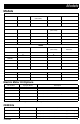
Models Models GH130 Model: Standard 120V Motor Kit (Non CSA) 24W923 24W924 Model: Standard ProContractor 24W925 24W926 GH200 120V Motor Kit (Non CSA) 24W927 24W928 GH230 Model: Standard 24W929 24W930 24W931 ProContractor 120V Motor Kit (Non CSA) 120V ETL/CSA/UL Motor Kit 24W932 24W933 24W934 GH300 Model: Standard 24W935 ProContractor 24W936 Electric Motor Kit Options Kit Number Sprayer Model Description 288474 GH13
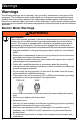
Warnings Warnings The following warnings are for the setup, use, grounding, maintenance, and repair of this equipment. The exclamation point symbol alerts you to a general warning and the hazard symbols refer to procedure-specific risks. When these symbols appear in the body of this manual or on warning labels, refer back to these Warnings. Product-specific hazard symbols and warnings not covered in this section may appear throughout the body of this manual where applicable.
Warnings WARNING FIRE AND EXPLOSION HAZARD Flammable fumes, such as solvent and paint fumes, in work area can ignite or explode. To help prevent fire and explosion: • Do not spray flammable or combustible materials near an open flame or sources of ignition such as cigarettes, motors, and electrical equipment. • Paint or solvent flowing through the equipment is able to result in static electricity. Static electricity creates a risk of fire or explosion in the presence of paint or solvent fumes.
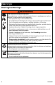
Warnings Gas Engine Warnings WARNING FIRE AND EXPLOSION HAZARD Flammable fumes, such as solvent and paint fumes, in work area can ignite or explode. To help prevent fire and explosion: • Use equipment only in well ventilated area. • Do not fill fuel tank while engine is running or hot; shut off engine and let it cool. Fuel is flammable and can ignite or explode if spilled on hot surface.
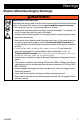
Warnings Electric Motor/Gas Engine Warnings WARNING SKIN INJECTION HAZARD High-pressure spray is able to inject toxins into the body and cause serious bodily injury. In the event that injection occurs, get immediate surgical treatment. • Do not aim the gun at, or spray any person or animal. • Keep hands and other body parts away from the discharge. For example, do not try to stop leaks with any part of the body. • Always use the nozzle tip guard. Do not spray without nozzle tip guard in place.
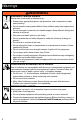
Warnings WARNING EQUIPMENT MISUSE HAZARD Misuse can cause death or serious injury. • Always wear appropriate gloves, eye protection, and a respirator or mask when painting. • Do not operate or spray near children. Keep children away from equipment at all times. • Do not overreach or stand on an unstable support. Keep effective footing and balance at all times. • Stay alert and watch what you are doing. • Do not operate the unit when fatigued or under the influence of drugs or alcohol.
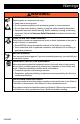
Warnings WARNING ENTANGLEMENT HAZARD Rotating parts can cause serious injury. • Keep clear of moving parts. • Do not operate equipment with protective guards or covers removed. • Do not wear loose clothing, jewelry or long hair while operating equipment. • Equipment can start without warning. Before checking, moving, or servicing equipment, follow the Pressure Relief Procedure and disconnect all power sources.
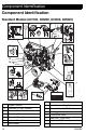
Component Identification Component Identification Standard Models (GH130, GH200, GH230, GH300) 2. 1. 3. 4. 5. bar/MPa PSI 6. 15. on F OF ON off 14. 13. 9. 7. 12. 8. 10. 9. 11.
Component Identification Component Identification ProContractor Models (GH200, GH230, GH300) 1. 2. 3. 4. on off bar/MPa PSI 17. 5. 6. F OF ON 7. 16. 15. 11. 14. 8. ti25106a 10. 9. 12. 11. 13.
Component Identification Grounding Procedure for Gas Engine Grounding Procedure for Electric Motor The equipment must be grounded to reduce the risk of static sparking. Static sparking can cause fumes to ignite or explode. Grounding provides an escape wire for the electric current. The equipment must be grounded to reduce the risk of static sparking and electric shock. An electric or static spark can cause fumes to ignite or explode. An improper ground can cause electric shock.
Pressure Relief Procedure Grounding of Pails Pressure Relief Procedure Follow the Pressure Relief Procedure whenever you see this symbol. Solvent pails used when flushing: Follow local code. Use only conductive metal pails, placed on a grounded surface. Do not place the pail on a non-conductive surface, such as paper or cardboard, which interrupts grounding continuity. ti25360a Always ground a metal pail: connect a ground wire to the pail.
Setup Setup Change Engine or Motor 1 3 Tilt engine/motor. Install engine/motor. Install belt. Lower belt guard. Turn motor OFF and unplug or turn engine switch OFF. Loosen belt guard knob and motor clamp. Perform Pressure Relief Procedure, page 13. WL D 4 OFF WL D Swivel motor clamp. Tighten motor clamp and belt guard knob. ON WL E ti5382a 2 ti5405a ti5387a ti5384a ti5389a Lift belt guard. Remove belt. Tilt engine/motor and remove engine/motor.
Setup Complete Setup 1. 5. All sprayers except ProContractor: Connect appropriate Graco high-pressure hose to sprayer. ProContractor Series: Install inlet strainer into bottom of suction tube, place inlet nut over end and hand tighten securely. Standard Series: Screw inlet strainer to bottom of suction hose and hand tighten securely. WL D 2. Install hose to spray gun and tighten securely. ti9126a ti8714a 6. When spraying texture, remove inlet strainer and filter bowl screen.
Setup 7. Fill throat packing nut with TSL to prevent premature packing wear. Do this each time you spray. 10. Check hydraulic oil level. Add Graco Hydraulic Oil, ISO Grade 46, 169236 (5 gallon/18.9 liter) or 207428 (1 gallon/3.8 liter). Hydraulic tank capacity is 1.25 gallon (4.75 liters). $SSUR[LPDWH )LOO /HYHO WL D 8. Check engine oil level. ti5243a Safe Range (cold) 11. Attach sprayer grounding clamp to earth ground. FROG WL D 9. Fill fuel tank.
Startup Startup 1. Place suction tube and drain tube in grounded metal pail partially filled with flushing fluid. Attach ground wire to pail and to earth ground. 4. If using electric motor, plug cord into outlet and turn switch to ON. 5. If using gas engine, start engine. ti4296b a. Move fuel valve to open. ti5248a b. PAINT WL D 2. Move choke to closed. FLUSH Turn prime valve down to DRAIN position. Turn pressure control counterclockwise to lowest pressure. ti5249a c.
Startup d. h. Set engine switch to ON. Set hydraulic pump valve ON (hydraulic motor is now active). ti5262a ti9687a e. Pull starter rope. 6. Increase pressure enough to start hydraulic motor stroking and allow fluid to circulate for 15 seconds; turn pressure down, turn prime valve horizontal. ti5263a f. After engine starts, move choke to open. 15 SEC WL E 7. Disengage spray gun trigger lock. ti22818a ti5264a g. Set throttle to desired setting. 8.
Startup High-pressure spray is able to inject toxins into the body and cause serious bodily injury. Do not stop leaks with hand or rag. 9. Inspect for leaks. If leaks occur, turn sprayer OFF immediately. Perform Pressure Relief Procedure, page 13. Tighten leaky fittings. Repeat Startup procedure steps 2-8. If no leaks, continue to trigger gun until system is thoroughly flushed. 10. Place siphon tube in paint pail. PAINT ti5255a 11. Trigger gun again into flushing fluid pail until paint appears.
Startup Switch Tip™ and Guard Assembly 1. Perform Pressure Relief Procedure, page 13. 2. Engage gun trigger lock. Insert Switch Tip. Insert seat and OneSeal™. Spray 1. Spray test pattern. Increase pressure to eliminate heavy edges. Use smaller tip size if pressure adjustment can not eliminate heavy edges. ti13030a 2. Hold gun perpendicular, 10-12 in. (25-30 cm) from surface. Spray back and forth. Overlap by 50%. Trigger gun after moving and release before stopping. ti13023a 3.
Startup Clear Tip Clog 1. 1. Make sure hose is routed through hose guide. Release trigger, engage trigger lock. Rotate Switch Tip. Disengage trigger lock. Trigger gun to clear clog. ti25149a 2. Lift and turn pivot lock 90° to unlock hose reel. Pull on hose to remove it from hose reel. ti13033a 2. Engage trigger lock. Return Switch Tip to original position. Disengage trigger lock and continue spraying. ti22744a 3. Pull reel handle down and turn clockwise to reel in hose.
Clean Up Clean Up 1. Perform Pressure Relief Procedure, page 13, steps 1-7. 2. Remove Guard and SwitchTip. 5. Hold gun against pail. Disengage trigger lock. Turn pressure control up until motor begins to drive pump. Trigger gun until flushing fluid appears. PAINT ti8687a 3. Remove siphon tube set from paint and place in flushing fluid. Use water for water-based paint and mineral spirits for oil based paint. WL D 6. PAINT FLUSH FLUSH WL D 4.
Clean Up 8. Raise siphon tube above flushing fluid and run sprayer for 15 to 30 seconds to drain fluid. Turn hydraulic valve OFF. Turn engine OFF or turn electric motor OFF and unplug. 10. Depending on model, either remove nut and inlet strainer screen from bottom of suction tube, or unscrew and remove inlet strainer. Clean and replace strainer screen if necessary. Reassemble. PAINT FLUSH ti8840a ti9127a WL E 9. Engage trigger lock. Remove filters from gun and sprayer, if installed.
Maintenance Maintenance AFTER EACH 100 HOURS OF OPERATION: Change engine oil. Reference Honda Engines Owner's Manual for correct oil viscosity. SEMI-ANNUALLY: Check belt wear. Replace if necessary. NOTE: For detailed engine maintenance and specifications, refer to separate Honda Engines Owner’s Manual, supplied. DAILY: Check engine oil level and fill as necessary. DAILY: Check hydraulic oil level and fill as necessary. DAILY: Check hose for wear and damage.
Troubleshooting Troubleshooting Problem Cause Solution Gas engine pulls hard (won’t start) Hydraulic pressure is too high Turn hydraulic pressure knob counterclockwise to lowest setting Gas engine does not start Switch OFF, low oil, no gasoline Consult engine manual Fuel shut off valve closed Open fuel shut off valve Gas engine does not work properly Faulty engine Consult engine manual Elevation Refer to Engine Repair Kit, 4.0 hp - 288678 / 5.5 hp - 248943 / 6/5 hp - 248944 / 9.
Troubleshooting Problem Displacement pump operates, but output is low on down stroke and/or on both strokes Cause Solution Piston packings worn or damaged Tighten packing nut or replace packings. See manual 334654 Intake valve ball check not seating properly Service intake valve ball check. See manual 334654 Suction tube air leak Hydraulic oil filter is dirty Replace filter. Loose wet cup Tighten wet cup enough to stop leakage Throat packings worn or damaged Replace packings.
Standard Series Pump Standard Series Pump Removal 5. Loosen jam nut. Unscrew pump. See pump manual 334654 for pump repair. 1. Flush pump. 2. Perform Pressure Relief Procedure, page 13. 3. Remove suction tube and paint hose (remove at swivel end). ti2272c Installation NOTICE If pump jam nut loosens during operation, the threads of the bearing housing and drive train will be damaged. Tighten jam nut as specified. 1. ti2272a 4. Push retaining ring up; push out pin.
ProContractor Series Pump ProContractor Series Pump If pin is loose, parts could break off and project through the air, resulting in serious injury or property damage. Make sure pin is properly installed. 2. Slowly pull engine starter rope until pump rod pin hole is aligned with hydraulic rod hole. Push pin into hole. Push retaining ring into groove. Removal See pump manual 334654 for pump repair. 1. Flush pump. 2. Perform Pressure Relief Procedure, page 13. 3. Remove suction hose. ti2272e 3.
ProContractor Series Pump 5. Slide coupler cover up to fully expose rod couplers. 6. Remove rod couplers. 8. Open clamp. ti8829a ti8833a 9. Remove pump from unit. ti8830a 7. ti8832a Installation Remove pin. 1. If needed, place pump rod in adjustment casting and pull pump to extend rod. ti8831a NOTE: Support pump with your hand before opening t-handle. ti8834a 2. 334558B Reverse removal steps to reassemble pump.
Notes Notes 30 334558B
Parts Parts GH™130/200/230/300 Standard Series ti25097a 334558B 31
Parts Parts GH™130/200/230/300 Standard Series 1 Torque to 120-130 in-lbs (13.6-14.7 N·m) 2 Inflate tires to 25-35 psi (1.7-2.4 bar) 234 3 Torque to 110-120 in-lbs 234 233 (12.4-13.6 N·m) 4 Torque to 355-395 in-lbs 232 233 (40.1-44.6 N·m) 232 5 Torque to 15-25 in-lbs (1.7-2.8 N·m) 231 6 Loctite 242 63 7 Torque to 35-45 ft-lbs 63 (47.5-61.
Parts Parts List Ref. 35 39 54 57 58 59 60 61 Part Description 112827 BUTTON, snap 119420 WHEEL, pneumatic, GH130 & 200 119509 WHEEL, pneumatic, GH230 & 300 156306 WASHER, flat 15C780 HANDLE, GH130 15C972 PIN, grooved, GH130 224807 BASE, valve, GH130 235014 VALVE, replacement, kit, GH130 15E022 SEAT, valve, GH130 Qty.
Parts Parts - Engines GH™130/200/230 Standard Series 1 Torque to 120-130 in-lbs 90 (13.6-14.7 N·m) 88 119 2 Torque to 58-62 in-lbs (6.6-7.0 N·m) 126 106 3 Loctite 242 2 3 133 24 7 43 34 154 153 1 3 30 99 154 23 1 GH™300 Standard Series 88 90 119 1 Torque to 120-130 in-lbs (13.6-14.7 N·m) 2 Loctite 242 3 Torque to 58-62 in-lbs (6.6-7.
Parts Parts List Ref. Part 7 Description 100023 WASHER, flat, GH130, 200 & 230 100132 WASHER, flat, GH300 23 113664 SCREW, cap, hex hd, GH130, 200 & 230 106212 SCHREW, cap, hex hd, GH300 24 110838 NUT, lock, GH130, 200 & 230 101566 NUT, lock, GH300 30 108842 SCREW, cap, hex hd, GH130, 200 & 230 116645 SCREW, cap, hex hd, GH300 34 112717 WASHER, GH130, 200 & 230 119438 WASHER, GH300 43 116908 PULLEY, 5.
Parts Parts - Fan Belt GH™130/200/230/300 Standard Series 1 Torque to 120-130 in-lbs (13.6-14.7 N·m) 224 2 Loctite 242 225 4 5 223 3 Torque to 58-62 in-lbs (6.6-7.0 N·m) 226 222 4 Torque to 90-110 in-lbs 221 (10.2-12.4 N·m) 5 Loctite 277 44 6 Torque to 110-120 in-lbs (12.4-13.
Parts Parts List Ref.
Parts Parts GH™130/200/230/300 Standard Series 1 Torque to 70-80 ft-lbs (94.9-108.
Parts Parts List Ref.
Parts Parts GH™130/200/230/300 Standard Series Sprayers OEM Kits 2 272 293 271 266 1 1 246 245 244 243 283 143 239 283 239 289 242 3 1 Torque to 145-155 ft-lbs ti25128a (196.6-210.2 N·m) 2 Torque to 12-18 ft-lbs (16.3-24.4 N·m) 3 Torque to 140-160 in-lbs (15.8-18.
Parts Parts List Ref.
Parts Parts GH™130/200 Standard Series w/ Spray Gun and Hose Ref. Part No. Description 202 240794 HOSE, grounded, nylon; 1/4 in. ID;cpld 1/4-18 npsm; 50 foot (15 m); spring guards both ends 3300 psi (227 bar, 22.7 MPa) 288420 Contractor Spray Gun 203 Qty. 1 203 1 ® Includes 517 RAC X SwitchTip and HandTite™ Guard See 311861 for parts ti25435a 202 GH™230/300 Standard Series w/ Spray Gun and Hoses Ref. Part No. Description 202 287042 KIT, gun, Silver 3300 psi (227 bar, 22.
Parts Parts GH™200/230/300 ProContractor Series (OEM Kits) ti25104a 334558B 43
Parts Parts GH™200/230/300 ProContractor Series 1 Torque to 120-130 in-lbs (13.6-14.7 N·m) 2 Inflate tires to 25-35 psi (1.7-2.4 bar) 3 Torque to 110-120 in-lbs 234 (12.4-13.6 N·m) 4 Torque to 355-395 in-lbs 233 (40.1-44.6 N·m) 232 5 Torque to 15-25 in-lns (1.7-2.
Parts Parts List Ref.
Parts Parts - Engines GH™200/230 ProContractor Series 1 Torque to 120-130 in-lbs 90 (13.6-14.7 N·m) 88 119 2 Torque to 58-62 in-lbs (6.6-7.0 N·m) 126 106 3 Loctite 242 2 3 133 24 7 43 34 154 153 1 3 30 99 154 23 1 GH™300 ProContractor Series 88 90 1 Torque to 120-130 in-lbs 119 (13.6-14.7 N·m) 2 Loctite 242 3 Torque to 58-62 in-lbs (6.6-7.
Parts Parts List Ref. Part 7 Description 100023 WASHER, flat, GH200 & 230 100132 WASHER, flat, GH300 23 113664 SCREW, cap, hex hd, GH200 & 230 106212 SCHREW, cap, hex hd, GH300 24 110838 NUT, lock, GH200 & 230 101566 NUT, lock, GH300 30 108842 SCREW, cap, hex hd, GH200 & 230 116645 SCREW, cap, hex hd, GH300 34 112717 WASHER, GH200 & 230 119438 WASHER, GH300 43 116908 PULLEY, 5.
Parts Parts - Fan Belt GH™200/230/300 ProContractor Series 1 Torque to 120-130 in-lbs (13.6-14.7 N·m) 224 225 4 5 223 2 Loctite 242 3 Torque to 58-62 in-lbs 222 4 Torque to 90-110 in-lbs 221 (6.6-7.0 N·m) (10.2-12.4 N·m) 44 5 Loctite 277 6 Torque to 110-120 in-lbs (12.4-13.
Parts Parts List Ref.
Parts Parts GH™200/230/300 ProContractor Series 1 Torque to 90-110 in-lbs (10.2-12.
Parts Parts List Ref. Part Description Qty.
Parts Parts GH™200/230/300 ProContractor Series Sprayers OEM Kits 2 272 293 271 266 1 1 246 245 244 243 143 283 292 239 ti25456a 283 289 242 3 1 Torque to 145-155 ft-lbs (196.6-210.2 N·m) 2 Torque to 12-18 ft-lbs (16.3-24.4 N·m) 3 Torque to 140-160 in-lbs (15.8-18.
Parts Parts List Ref.
Parts Parts GH™200 ProContractor Series Spray Gun and Hoses (Assembled on Hose Reel) Ref. Part No. Description 202 240794 HOSE, grounded, nylon; 1/4 in. ID;cpld 1/4-18 npsm; 50 foot (15 m); spring guards both ends 3300 psi (227 bar, 22.7 MPa) 288420 Contractor Spray Gun 203 Qty. 2 202 203 1 Includes 517 RAC® X 204 SwitchTip and HandTite™ Guard See 311861 for parts 162453 ADAPTER 204 ti25447a 1 GH™230 ProContractor Series Spray Gun and Hoses (Assembled on Hose Reel) Ref. Part No.
Parts GH™300 ProContractor Series Spray Gun and Hoses (Assembled on Hose Reel) Ref. Part No. Description 302 240797 HOSE, grounded, nylon; 3/8 in. ID;cpld 3/8-18 npsm; 50 foot (15 m); spring guards both ends 3300 psi (227 bar, 22.7 MPa) 241735 HOSE, grounded, nylon; 1/4 in. ID; cpld 1/4 npt(m) x 1/4 npsm(f); 3 foot (0.9 m); spring guards both ends 3300 psi (227 bar, 22.7 MPa) 246240 Silver Spray Gun 303 304 Qty.
Technical Data Technical Data GH™130 Standard Series US Metric Maximum fluid working pressure . . . . . . . . 3300 psi 22.8 MPa, 228 bar Hydraulic reservoir capacity . . . . . . . . . . . . 1.25 gallons 4.75 liters Maximum hydraulic pressure . . . . . . . . . . . 1510 psi 10.4 MPa,104 bar Engine . . . . . . . . . . . . . . . . . . . . . . . . . . . . 120 cc (4.0 HP) 0.037 Maximum tip size . . . . . . . . . . . . . . . . . . . . Maximum free-flow delivery . . . . . . . . . . . . 1.
Technical Data GH™200 Standard Series US Metric Maximum fluid working pressure . . . . . . . . 3300 psi 22.8 MPa, 228 bar Hydraulic reservoir capacity . . . . . . . . . . . . 1.25 gallons 4.75 liters Maximum hydraulic pressure . . . . . . . . . . . 1855 psi 12.8 MPa,128 bar Engine . . . . . . . . . . . . . . . . . . . . . . . . . . . . 160 cc (5.5 HP) 0.047 Maximum tip size . . . . . . . . . . . . . . . . . . . . Maximum free-flow delivery . . . . . . . . . . . . 2.15 gpm Hose connection . .
Technical Data GH™230 Standard Series US Metric Maximum fluid working pressure. . . . . . . . . 3300 psi 22.8 MPa, 228 bar Hydraulic reservoir capacity . . . . . . . . . . . . 1.25 gallons 4.75 liters Maximum hydraulic pressure . . . . . . . . . . . 1855 psi 12.8 MPa,128 bar Engine . . . . . . . . . . . . . . . . . . . . . . . . . . . . . 200 cc (6.5 HP) 0.053 Maximum tip size. . . . . . . . . . . . . . . . . . . . . Maximum free-flow delivery. . . . . . . . . . . . . 2.
Technical Data GH™300 Standard Series US Metric Maximum fluid working pressure . . . . . . . . 3300 psi 22.8 MPa, 228 bar Hydraulic reservoir capacity . . . . . . . . . . . . 1.25 gallons 4.75 liters Maximum hydraulic pressure . . . . . . . . . . . 1855 psi 12.8 MPa,128 bar Engine . . . . . . . . . . . . . . . . . . . . . . . . . . . . 270 cc (9.0 HP) 0.057 Maximum tip size . . . . . . . . . . . . . . . . . . . . Maximum free-flow delivery . . . . . . . . . . . . 3.0 gpm Hose connection . . .
Technical Data GH™200 ProContractor Series US Metric Maximum fluid working pressure. . . . . . . . . 3300 psi 22.8 MPa, 228 bar Hydraulic reservoir capacity . . . . . . . . . . . . 1.25 gallons 4.75 liters Maximum hydraulic pressure . . . . . . . . . . . 1855 psi 12.8 MPa,128 bar Engine . . . . . . . . . . . . . . . . . . . . . . . . . . . . . 160 cc (5.5 HP) 0.047 Maximum tip size. . . . . . . . . . . . . . . . . . . . . Maximum free-flow delivery. . . . . . . . . . . . . 2.
Technical Data GH™230 ProContractor Series US Metric Maximum fluid working pressure . . . . . . . . 3300 psi 22.8 MPa, 228 bar Hydraulic reservoir capacity . . . . . . . . . . . . 1.25 gallons 4.75 liters Maximum hydraulic pressure . . . . . . . . . . . 1855 psi 12.8 MPa,128 bar Engine . . . . . . . . . . . . . . . . . . . . . . . . . . . . 200 cc (6.5 HP) 0.053 Maximum tip size . . . . . . . . . . . . . . . . . . . . Maximum free-flow delivery . . . . . . . . . . . . 2.
Technical Data GH™300 ProContractor Series US Metric Maximum fluid working pressure. . . . . . . . . 3300 psi 22.8 MPa, 228 bar Hydraulic reservoir capacity . . . . . . . . . . . . 1.25 gallons 4.75 liters Maximum hydraulic pressure . . . . . . . . . . . 1855 psi 12.8 MPa,128 bar Engine . . . . . . . . . . . . . . . . . . . . . . . . . . . . . 270 cc (9.0 HP) 0.057 Maximum tip size. . . . . . . . . . . . . . . . . . . . . Maximum free-flow delivery. . . . . . . . . . . . . 3.
Technical Data Technical Data GH200 OEM GH130 OEM Hydraulic Return, 37º flare, 3/4-16 UNF-2A Hydraulic Inlet, 37º flare, 3/4-16 UNF-2A Hydraulic Return, 37º flare, 3/4-16 UNF-2A Hydraulic Inlet, 37º flare, 3/4-16 UNF-2A GH230/300 OEM Mounting Screws (4), Socket Cap Screw 1 in. 3/8-16 UNC Hydraulic Return, 37º flare, 3/4-16 UNF-2A Hydraulic Inlet, 37º flare, 3/4-16 UNF-2A 2.25 in. (57.15 mm) 1.813 in. (46.05 mm) 2.25 in. (57.15 mm) Mounting Screw (4), Socket Cap Screw 1in.
Graco Standard Warranty Graco Standard Warranty Graco warrants all equipment referenced in this document which is manufactured by Graco and bearing its name to be free from defects in material and workmanship on the date of sale to the original purchaser for use. With the exception of any special, extended, or limited warranty published by Graco, Graco will, for a period of twelve months from the date of sale, repair or replace any part of the equipment determined by Graco to be defective.
Graco Information For the latest information about Graco products, visit www.graco.com. For patent information, see www.graco.com/patents. TO PLACE AN ORDER, contact your Graco distributor or call 1-800-690-2894 to identify the nearest distributor. All written and visual data contained in this document reflects the latest product information available at the time of publication. Graco reserves the right to make changes at any time without notice. Original instructions. This manual contains English.