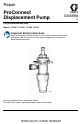
Repair ProConnect Displacement Pump 334599A For professional use only. Models: 17C487, 17C488, 17C489, 17C721 Important Safety Instructions Read all warnings and instructions in this manual and related manuals. Be familiar with the controls and the proper usage of the equipment. Save these instructions. ti24850a Use only genuine Graco replacement parts. The use of non-Graco replacement parts may void warranty.
Contents Contents Warnings . . . . . . . . . . . . . . . . . . . . . . . . . . . . . . . . . . . . . . . . . . . . . . . . . . . . . . . . . . . . . 3 Repair . . . . . . . . . . . . . . . . . . . . . . . . . . . . . . . . . . . . . . . . . . . . . . . . . . . . . . . . . . . . . . . . 5 Trigger Lock . . . . . . . . . . . . . . . . . . . . . . . . . . . . . . . . . . . . . . . . . . . . . . . . . . . . . . . . 5 Pressure Relief Procedure . . . . . . . . . . . . . . . . . . . . . . . . . . . . . . . . . . .
Warnings Warnings The following warnings are for the setup, use, grounding, maintenance, and repair of this equipment. The exclamation point symbol alerts you to a general warning and the hazard symbols refer to procedure-specific risks. When these symbols appear in the body of this manual or on warning labels, refer back to these Warnings. Product-specific hazard symbols and warnings not covered in this section may appear throughout the body of this manual where applicable.
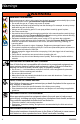
Warnings WARNING SKIN INJECTION HAZARD High-pressure spray is able to inject toxins into the body and cause serious bodily injury. In the event that injection occurs, get immediate surgical treatment. • Do not aim the gun at, or spray any person or animal. • Keep hands and other body parts away from the discharge. For example, do not try to stop leaks with any part of the body. • Always use the nozzle tip guard. Do not spray without nozzle tip guard in place. • Use Graco nozzle tips.
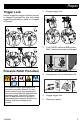
Repair 1. Trigger Lock Repair Engage trigger lock. Always engage the trigger lock when sprayer is stopped to prevent the gun from being triggered accidentally by hand or if dropped or bumped. ti24851a 2. Turn ON/OFF switch to OFF position. Wait 7 seconds for power to dissipate. ti24612a ti24852a Pressure Relief Procedure 3. This equipment stays pressurized until pressure is manually relieved.
Repair 6. Turn pressure control to lowest setting. Disengage trigger lock. 8. ti24855a ti24854a 7. Hold a metal part of the gun firmly to a grounded metal pail. Trigger the gun to relieve pressure. Engage trigger lock. 9. Open any fluid drain valves in system. Leave drain valves open until ready to spray again.
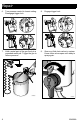
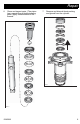
Repair Dissemble Pump 1. 3. Remove packing nut and throat adjustment spacer. Retaining nuts are not removable and not sold separately. Dissemble intake valve. Clean and inspect. O-ring may require a pick for removal. NOTICE If using a pick to remove the O-ring use care to avoid damage to the machined surfaces. Retaining Nuts ti24863a ti24874a 2. Unscrew cylinder from intake valve.
Repair 4. Tap piston rod out of cylinder with a hammer or flip over and tap piston rod out against a bench. Do not clean or wipe the piston valve threads. Cleaning the piston valve threads could destroy the special sealing patch and cause the piston valve to come loose during operation, causing a pump burst and possible serious bodily injury. 5. Unscrew piston valve from piston rod.
Repair 6. Clean and inspect parts. (The piston has a special thread locking/sealing patch. Apply thread sealant to the threads. 7. Remove and discard throat packing and glands from the cylinder.
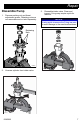
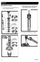
Repair Assemble Pump 1. 2. Soak leather packings in SAE 30W oil for one hour before assembly. Install ball in piston rod. If thread sealant is applied to piston valve threads, ensure that none gets on the ball. Leather Packings ti24891a 3. ti24890a Torque to 27 ± 3 ft-lb (37 ± 4 N•m).
Repair 4. Assemble leather throat packings soaked earlier. 6. Apply liberal amounts of grease or oil to piston packings. Leather Packings ti24895a 7. ti24893a 5. Grease top inch or two of piston rod that will go through the cylinder throat packings. Gently guide displacement rod up through throat packings. Tap bottom of piston valve as necessary with a leather or plastic hammer. Loosely install packing nut with o-ring onto cylinder.
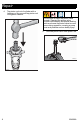
Repair 8. Grease o-ring and place on outside diameter ring groove. 10. Torque to 60 ± 5 ft-lb (81 ± 7 N•m). ti24897a 9. Clean seat thoroughly. Reassemble intake valve with a seat, ball, and new o-ring. Seat may be flipped over and used on other side.
Repair 11. Install o-ring onto packing nut. Torque to 75 ± 5 ft-lb (101.7 ± 6.8 N•m) or additional 1/2 turn from hand tight. 12.
Repair Throat Packing Adjustment When pump packings begin to leak after much use, perform Pressure Relief Procedure, page 5 and tighten packing nut down until leakage stops or lessens. This allows approximately 100 gallons of additional operation before a repacking is required. Packing nut can be tightened without o-ring removal. This equipment stays pressurized until pressure is manually relieved.
Parts Parts 202 208 203 223 220 224 204 222 221 209 211 207 205 201 212 213 218 225 215 217 229 216 206 219 ti24903a 334599A 15
Parts Parts List Ref. 201 Part Description Qty. 24W617 ROD, displacement, 1 includes 212 202* 180656 BUTTON, plug 1 203 193047 NUT, packing 1 204* 176757 GLAND, female, throat 1 205* 176754 GLAND, male throat 1 206 24W619 CYLINDER, pump 1 includes retaining nuts 229 207* 105444 BALL, sst, 0.3125 in.
Pump Installation Pump Installation Pump installation includes securing the pump and connecting to the fluid inlet and outlet. 1. Connect outlet hose to pump. ti24087a 5. Use both hands to tighten pump retaining nut. ti24086a 2. Move pump displacement rod up or down until it slides into the connecting rod when the pump is slid into the drive housing. ti24088a 6. Use a hammer to turn pump retaining nut an additional 1/8 to 1/6th turn or 45° to 60°. ti24085a 3.
Technical Specifications Technical Specifications PC Displacement Pump Maximum fluid working pressure Inlet/Outlet Sizes Fluid inlet size Fluid outlet size Wetted materials on all models 18 US 3300 psi Metric 228 bar, 22.8 MPa 1.0 in. diameter 2.54 cm diameter 1/4 in. 6.
Graco Standard Warranty Graco Standard Warranty Graco warrants all equipment referenced in this document which is manufactured by Graco and bearing its name to be free from defects in material and workmanship on the date of sale to the original purchaser for use. With the exception of any special, extended, or limited warranty published by Graco, Graco will, for a period of twelve months from the date of sale, repair or replace any part of the equipment determined by Graco to be defective.
Graco Information For the latest information about Graco products, visit www.graco.com. For patent information, see www.graco.com/patents. TO PLACE AN ORDER, contact your Graco distributor or call 1-800-690-2894 to identify the nearest distributor. All written and visual data contained in this document reflects the latest product information available at the time of publication. Graco reserves the right to make changes at any time without notice. Original instructions. This manual contains English.