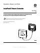
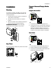
Operation, Repair, and Parts InvisiPac® Pattern Controller 334784A EN To control fluid dispense valves of adhesive supply equipment. For professional use only. Not approved for use in explosive atmospheres or hazardous locations. Important Safety Instructions. Read all warnings and instructions in this manual and related manuals. Save these instructions. See page 3 for model information and Agency approvals. PROVEN QUALITY. LEADING TECHNOLOGY.
Contents Models............................................................... 3 Agency Approvals............................................... 3 Related Manuals ................................................ 3 Warnings ........................................................... 4 Overview............................................................ 7 Component Identification..................................... 8 Installation.......................................................... 9 Mounting ..........
Models Models Usage Part Type With InvisiPac 24X523 PC-8 24X524 PC-8e 24X525 PC-8 24X526 PC-8e Without InvisiPac Description Contents Time or distance mode, no encoder 127971 — Pattern Controller Time or distance mode, with or 127971 — Pattern Controller without encoder Run up control (optional) 24X626 — Key Token for Encoder and Run up Time or distance mode, no encoder 127971 — Pattern Controller 24P860 — Advanced Display Module Time or distance mode, with or without encoder Run up control (
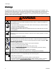
Warnings Warnings The following warnings are for the setup, use, grounding, maintenance, and repair of this equipment. The exclamation point symbol alerts you to a general warning and the hazard symbols refer to procedure-specific risks. When these symbols appear in the body of this manual or on warning labels, refer back to these Warnings. Product-specific hazard symbols and warnings not covered in this section may appear throughout the body of this manual where applicable.
Warnings WARNING EQUIPMENT MISUSE HAZARD Misuse can cause death or serious injury. • Do not operate the unit when fatigued or under the influence of drugs or alcohol. • Do not exceed the maximum working pressure or temperature rating of the lowest rated system component. See Technical Data in all equipment manuals. • Use fluids and solvents that are compatible with equipment wetted parts. See Technical Data in all equipment manuals. Read fluid and solvent manufacturer’s warnings.
Warnings WARNING PERSONAL PROTECTIVE EQUIPMENT Wear appropriate protective equipment when in the work area to help prevent serious injury, including eye injury, hearing loss, inhalation of toxic fumes, and burns. This protective equipment includes but is not limited to: • Protective eyewear, and hearing protection. • Respirators, protective clothing, and gloves as recommended by the fluid and solvent manufacturer.
Overview Overview InvisiPac Pattern Control systems can be integrated with InvisiPac systems or stand alone with any other equipment. For all installations, the Advanced Display Module (ADM) is used to make programming easy. PC-8 controllers operate in time or distance mode without an encoder. Up to 8 guns and 4 independent triggers are supported.
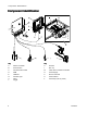
Component Identification Component Identification Key A Pattern Controller Key K B Encoder Power Switch L Run Up C D Communication Cable ADM E Inside View of Pattern Controller Power Supply Ground Terminal G H USB Port Indicator Light Valve M N P S T Control Board Cord Grips (I/O x2, power) J Trigger 8 334784A
Installation Installation Connect Advanced Display Module (ADM) Mounting Integrate with InvisiPac The Pattern Controller and ADM can be mounted using the included VESA-compatible bracket and mounting hardware. 1. Unscrew the two lower screws to uncouple the “wall” portion of the bracket. 2. Securely mount the bracket in the desired location. 3. Slide the controller onto the bracket and tighten the two screws for permanent fastening.
Installation Valve Installation Trigger Installation 1. Connect up to 4 NPN, PNP, or dry contact triggers. 1. Connect up to 8 valves. NOTE: Supplied voltage (+) is 24 VDC. NOTE: Control voltage is 24 VDC with a limit of 1 amp per output and 6 amps total. NOTE: Green LEDs indicate the status of each valve. Standard Wiring Colors Function M8 or M12 Cable Terminal Cable Black/Blue M12 Plus (+) 24V Supply Minus ( - ) Return Brown/Blue M8 2.
Installation PLC Inputs and Outputs Installation (optional) 1. Integrate with a PLC by using these inputs and outputs. 2. Inputs are bipolar and accept a 0 VDC to 30 VDC signal. Each input is electrically isolated. To connect a dry contact signal, route 24 VDC to one terminal and connect the ground through the dry contact to the other terminal. 3. Outputs are dry contact and open in the case of an alarm.
Installation (PC--8e only) Encoder Installation (PC (PC--8e only) Run Up Installation (PC 1. Connect up to two “I/P” or “V/P” run-up air pressure regulators to vary pump pressure based on line speed. Hardware automatically detects whether an I2P or V2P is connected. NOTE: Pressure vs. line speed settings are entered on the run-up setup screen (see Run Up Control (Screens 6–7, PC–8e only), page 26). 1. Connect up to two encoders to monitor line speed.
Installation Connect Electrical Cord 1. Install power wires (L1/L2 or L/N) into terminals 2 and 4 on the disconnect switch. The switch accepts solid or stranded 12 AWG and 14 AWG wire. For ratings, see Technical Data, page 46. 2. Connect earth ground to the grounding terminal. Improper wiring may cause electric shock or other serious injury if work is not performed properly. Have a qualified electrician perform any electrical work.
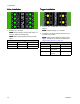
Screens Screens Navigate through each screen to set up the Pattern Controller interface. • Run screens include the home page and pattern definition. • Setup screens contain configurable settings for each accessory. Screen Maps NOTE: On integrated InvisiPac system, additional chapters are present for hot melt HMI. Run Screens PC Control PC Home Events Errors 1. Program Storage 2. Pattern Definition Press to switch between Run and Setup Setup Screens PC Setup Advanced 1. Event Map 1. Display 2.
Screens HMI Interface Key BA Controller Enable/Disable BC BD Stop all system processes Defined by icon next to soft key Abort current operation Accept change, acknowledge error, select item, toggle selected item Toggle between Run and Setup screens Navigate within a screen or to a new screen BE BF BG BH 334784A Function 15
Screens PC Screens Home Read only view of pattern controller inputs and outputs: 1. Status of guns , triggers , and PLC signals. 2. Production rate , and units completed 3. Material dispensed per product . . A — Gun States B — Trigger States C — Line Information D — PLC Signals Icon Name Description Gun Gun status: Active (green), Enabled (gray), Disabled (crossed out). Trigger Trigger Status: Active (bright yellow), Inactive (dark yellow).
Screens Program Storage (Screen 1) 1. Select program to load. 2. Copy program 3. Purge guns , erase program , or rename program . . . 4. Lock/unlock controller for maintenance NOTE: Copy, erase, and rename capabilities are disabled if “Lock Pattern Definition” is enabled (see General Setup (Screen 4), page 24).
Screens Gun Purge 1. Purge individual guns . 2. Purge all guns by pressing enter . NOTE: Only guns with assigned triggers will purge. NOTE: Guns may only be purged when the system is active or within 5 minutes of the system being active.
Screens Pattern Definition (Screen 2) 1. Enter start point and length of beads. 2. Enable or disable stitching for each bead. 3. Preview this pattern. NOTE: To clone the pattern from gun A to gun B, navigate to any bead on gun B and press/hold the number key for gun A. NOTE: Enter the screen and scroll down to see valves 5–8. Add beads and continue to scroll right to access beads 6–24.
Screens Pattern Preview Read-only display of bead pattern. A — Endpoint of Last Bead B — Exit Preview — Gun Number — Trigger Number NOTE: Dotted pattern shows stitching. The actual number of stitched beads is not represented. NOTE: A red dotted pattern indicates that the gun does not have a trigger selected (see Event Map (Screen 1), page 21).
Screens Event Map (Screen 1) Enter configuration settings for this pattern: 1. Assign trigger to each gun. 2. Input gun-to-trigger offset. 3. Enter minimum product length (if false trigger pickup is a concern). 4. Enable pattern mirroring. 5. Enter stitch percentage and interval.
Screens Line Mode (Screen 2) last product 1. Select mode: is correct. 4. For distance mode with encoder. a. Time based. b. Distance mode without encoder (uses fixed line speed). c. until length of b. Adjust line speed setting Distance mode with encoder. 2. For time mode, there are no additional settings. a. Verify positive line speed when line is moving forward. If speed is negative, swap A and A’ with B and B’ wires at the encoder connector on the Pattern Controller. b.
Screens Trigger Setup (Screen 3) 1. Select Trigger Polarity b. Where two line speed settings are required, select line 1 for triggers sensing from the first line speed and line 2 for the second. : a. Trigger should show bright yellow when product is present and dark yellow for no product. 3. Trigger Cycle Counters: a. View current and lifetime cycle counts of each trigger. b. If polarity is backwards, use the drop-down to reset current cycle b. Press soft key count of selected trigger.
Screens General Setup (Screen 4) 1. Lock Pattern Definition (optional) — Protects pattern from accidental changes. Operator must enter a password to change patterns, and copy, delete, or rename programs. NOTE: This setting will only take effect if Run Screens are also locked (see Advanced Screens, page 27). 2. Enable Pressure Compensation (optional, PC-8e only): • Used to maintain consistent glue output with variable line speed. 3.
Screens Gun Setup (Screen 5) • View current and lifetime cycle counts of each gun. 1. Gun Compensation: • Enter gun open compensation . • Enter gun close compensation . to reset current cycle • Press soft key counter of selected gun. 2.
Screens Run Up Control (Screens 6–7, PC–8e only) • Enter run up output settings A — Enter Screen B — Minimum Output C — Maximum Output D — High Calibration Point E — Low Calibration Point P — Screen Number (Screen 6) Icon 26 Name Description Output Pressure Percentage Line Speed Enter minimum and maximum pressure for run up control. Enter corresponding pressure points for entered line speed points to set run up curve.
Screens Advanced Screens Advanced — Display Advanced — Units General display settings including language, time, and password protection. Select the system units to be used on the display. Name Name Language Date Format Description Date Select the display language Select the display date format Enter the display date Time Enter the display time Password Enter the password to restrict access to Setup screens. NOTE: A value of “0000” does not require a password for access to setup screens.
Screens Advanced — USB Downloads Settings Advanced — System Software Select USB download settings. Read only display of system software.
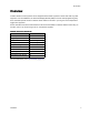
Stitching Stitching To maintain bond strength while reducing adhesive consumption.. Definitions Sub-Bead — One dispense cycle of a stitched bead. Stitch Interval — The distance between the starts of two adjacent sub-beads. Stitch Savings — The percentage of adhesive saved. Anchor Beads An anchor bead is a sub-bead placed at the end of the stitched bead that guarantees the stitched bead ends at the same location as the original (non-stitched) bead. Setup 3.
Line Speed Line Speed 1. Navigate to Line Mode (Screen 2), page 22. 2. Pass a product of known length past the trigger in use. 3. Once the product has passed the trigger, note the value displayed in the Last Product Length indicator. NOTE: This value is the length of the part of the product that passes below the trigger in use, not necessarily the overall length of the product. 4. Adjust settings: a.
Run Up Control Run Up Control Run Up Setup User Setting Entry 1. Verify run up controller range is set to 100 psi (10 V input signal yields 100 psi). NOTE: settings below assume input air pressure to the regulator is greater than or equal to 100 psi (simplifies run up programming so that % and psi values are interchangeable). 1. Navigate to Run Up Control (Screens 6–7, PC–8e only), page 26. Enter settings in screenshot according to values in section below. 2.
Run Up Control Random Length Bead Mode For handling products of various lengths with one pattern To use random length bead mode, perform the following steps: 1. Navigate to Event Map (Screen 1), page 21. 2. Select Mirror Bead Pattern gun. for the desired 3. Verify the appropriate Gun-Trigger Offset for the selected gun. 5. Enter the leading margin (LM) in the bead 1 offset box. NOTE: The leading margin is equal to the trailing margin. 6.
Run Up Control Mirror Mode For symmetrical patterns, including products with varying lengths. 2. Select Mirror Bead Pattern gun. for the desired for the selected 3. Verify Gun-Trigger Offset gun is greater than or equal to the end of the final bead (final bead offset + length). 4. Navigate to Pattern Definition (Screen 2), page 19. To use mirror mode, perform the following steps: 5. Enter bead information for the first half of the product. 1. Navigate to Event Map (Screen 1), page 21. 6.
Calibration Calibration Recommended Values GM-100: 5-10 ms GS-35: 10–20 ms Unknown, other: 10 ms Gun Compensation (optional) Calibration Routine For high speed lines and precision applications. 1. Navigate to Gun Setup (Screen 5), page 25. NOTE: Before entering gun compensation values, ensure the appropriate gun-trigger offset values have been entered for each gun-trigger pair on Event Map (Screen 1), page 21. 2. Dispense desired pattern (program contained within the Pattern Controller). 3.
Verification Verification Encoder 1. Navigate to Home, page 16. This section verifies proper installation of the InvisiPac Pattern Control System. For further assistance, see Troubleshooting, page 36. Valves 1. Navigate to Gun Purge, page 18. 2. Verify that the line speed displayed in the Current Line Speed indicator for different line speeds. is positive and varies 3. If the line speed shown does not match the known/expected value, see Calibration, page 34, to make the appropriate adjustments. a.
Troubleshooting Troubleshooting Error Codes When error occur, press to acknowledge each error. After being acknowledged, the error will clear automatically when the condition that caused it is corrected. Active errors scroll on the menu bar Alarms shut down the Pattern Controller and activate the dry contact PLC output. Advisories and deviations are informational only and do not shut the system down.
Troubleshooting Display Problem Display does not turn on Cause Selector dial on Pattern Control board set to wrong position Solution Integrated Systems: set to 0 Stand-Alone Systems: set to 1 Check for green light on Pattern Control board and Display Communication cable disconnected Verify Pattern Control board is connected to Display Selector dial on Pattern Control Integrated Systems: set to 0 board set to wrong position Stand-Alone Systems: set to 1 Software version mismatch Perform software update p
Troubleshooting Valve Problem System reset when guns fire No glue dispensed Cause Solution Current draw from combined Ensure current draw is below 6A total between all valves exceeds power supply simultaneously firing valves. rating (150 W) Ensure proper wiring between solenoid and Solenoid shorted pattern controller. If no shorts found, consider replacing solenoid.
Troubleshooting Run Up Problem Cause Run Up Controller reads 0 Integrated systems: InvisiPac system is INACTIVE psi Run Up Controller produces undesired results Solution Integrated systems: Turn system ON, run up will be active once system is ACTIVE (pump will turn on) Stand-Alone systems: PC system is INACTIVE Stand-Alone systems: Turn system ON, run up controller will Ensure pressure is being supplied to the No pressure to inlet of run up inlet of run up controller (check for valves controller and sh
Software Update Procedure Software Update Procedure When software is updated on the ADM the software is then automatically updated on all connected GCA components. A status screen is shown while software is updating to indicate progress. NOTE: When the screen turns on, you will see the following screens: First: Software is checking which GCA modules will take the available updates. 1. Turn system main power switch OFF. Second: 2. Remove ADM from bracket.
USB Download USB Download The system can store 250,000 entries in its logs and the system adds a new entry to the logs every 15 seconds. This means the system stores 1041 hours of system operation data, or 43 days of around-the-clock operation. Once full, the system will overwrite the oldest data. NOTE: To prevent losing any data, never go more than 43 days without downloading the logs. Download Procedure NOTICE Uploading an edited system configuration file can damage the system.
Parts Parts 42 334784A
Parts Parts List Ref. 1 Part Description Qty. 1 5 127886 6 7 126881 126891 ENCLOSURE, PC, painted FOAM, gasket LABEL, pattern controller LABEL, symbol, ground GROMMET, pattern controller BUSHING, strain relief NUT, bushing 8 114421 BUSHING, strain relief 1 FASTENER, hex, standoff TOOL, screwdriver 4 BLOCK, ground 1 15 WASHER, lock, ext 2 16 NUT, #8–32 hex 2 MODULE, GCA, pattern control SCREW, machine, ph, 8 x 3/8 in.
Parts Kits Kits List Part 24X446 Description KIT, photoeye, diffuse, 18mm Contents 128073 - SENSOR, photoelectric diffuse 128070 - BRACKET, sensor mount, angled 128071 - BRACKET, sensor mount, straight 24X447 KIT, photoeye, pol ret ref, 18mm 128081 - CABLE, M12, 4-pin, 5.
Wiring Diagram Wiring Diagram Ref. 9 Part 15U423 10 127887 14 334784A Description SWITCH, 2P, 25 A POWER SUPPLY, 24 DC, 6.3 A, 150 W HARNESS, ground Qty. 1 1 1 Ref. 28 Part Description 38 CONNECTOR, plug, 3 position TERMINAL, fork, #8 39 TERMINAL, fork, #4 Qty.
Technical Data Technical Data Description Gun Outputs Trigger Inputs Encoder Run Up Control Value 8 4 Details 24 VDC, 1A each, 6A max total NPN or PNP or Dry Contact 2 (PC-8e only) Quadrature differential line driver 2 (PC-8e only) I/P (4–20mA) or V/P (0–10V) PLC Enable/Disable PLC Program Select Bit YES 4 0–30 VDC, min 10V to assert Select up to 15 unique programs PLC Alarm Output YES Integrated Power Supply YES 0–250 VAC (dry contact output) Input: 100–240 VAC, 50/60 Hz Output: 24 VDC, 150
Notes Notes 334784A 47
Graco Standard Warranty Graco warrants all equipment referenced in this document which is manufactured by Graco and bearing its name to be free from defects in material and workmanship on the date of sale to the original purchaser for use. With the exception of any special, extended, or limited warranty published by Graco, Graco will, for a period of twelve months from the date of sale, repair or replace any part of the equipment determined by Graco to be defective.