
User's Manual

Installation
Valve Valve
Valve
Installation Installation
Installation
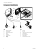
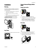
1.Connectupto8valves.
NOTE: NOTE:
NOTE:
Controlvoltageis24VDCwithalimitof1
ampperoutputand6ampstotal.
NOTE: NOTE:
NOTE:
GreenLEDsindicatethestatusofeach
valve.
Standard Standard
Standard
Wiring Wiring
Wiring
Colors Colors
Colors
Terminal Terminal
Terminal
Cable Cable
Cable
Function Function
Function
M8 M8
M8
or or
or
M12 M12
M12
Cable Cable
Cable
Plus(+)24VSupply
Black/BlueM12
Minus(-)
ReturnBrown/BlueM8
Trigger Trigger
Trigger
Installation Installation
Installation
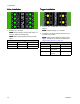
1.Connectupto4NPN,PNP,ordrycontact
triggers.
NOTE: NOTE:
NOTE:
Suppliedvoltage(+)is24VDC.
2.ConnectthetwowiresbetweenTRandminus(-)
toinstalladrycontact.
NOTE: NOTE:
NOTE:
YellowLEDsindicatethestatusofeach
trigger.Polaritycanbeinvertedifneeded(see
TriggerSetup(Screen3),page23).
Standard Standard
Standard
Wiring Wiring
Wiring
Colors Colors
Colors
Terminal Terminal
Terminal
Function Function
Function
M8 M8
M8
or or
or
M12 M12
M12
Cable Cable
Cable
Plus(+)24VSupply
Brown
TRNPN,PNP,or
DryContact
BlackorWhite
Minus(-)Return(orDry
Contact)
Blue
10 334784A