Operation Reactor® 2 Hydraulic Proportioning Systems 334945B Hydraulic, Heated, Plural Component Proportioner for spraying polyurethane foam and polyurea coatings. Not for outdoor use. For professional use only. Not approved for use in explosive atmospheres or hazardous locations. Important Safety Instructions Read all warnings and instructions in this manual. Save these instructions. For model information, see page 9. PROVEN QUALITY. LEADING TECHNOLOGY.
Contents Warnings ........................................................... 3 Startup............................................................... 44 Important Isocyanate Information......................... 7 Fluid Circulation.................................................. 47 Circulation Through Reactor ......................... 47 Circulation Through Gun Manifold ................. 48 Models............................................................... 9 Approvals...............................
Warnings Warnings The following warnings are for the setup, use, grounding, maintenance, and repair of this equipment. The exclamation point symbol alerts you to a general warning and the hazard symbols refer to procedure-specific risks. When these symbols appear in the body of this manual or on warning labels, refer back to these Warnings. Product-specific hazard symbols and warnings not covered in this section may appear throughout the body of this manual where applicable.
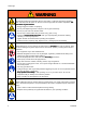
Warnings WARNING SKIN INJECTION HAZARD High-pressure fluid from dispensing device, hose leaks, or ruptured components will pierce skin. This may look like just a cut, but it is a serious injury that can result in amputation. Get immediate surgical treatment. • • • • • Engage trigger lock when not spraying. Do not point dispensing device at anyone or at any part of the body. Do not put your hand over the fluid outlet. Do not stop or deflect leaks with your hand, body, glove, or rag.
Warnings WARNING PRESSURIZED ALUMINUM PARTS HAZARD Use of fluids that are incompatible with aluminum in pressurized equipment can cause serious chemical reaction and equipment rupture. Failure to follow this warning can result in death, serious injury, or property damage. • Do not use 1,1,1-trichloroethane, methylene chloride, other halogenated hydrocarbon solvents or fluids containing such solvents. • Many other fluids may contain chemicals that can react with aluminum.
Warnings WARNING EQUIPMENT MISUSE HAZARD Misuse can cause death or serious injury. • Do not operate the unit when fatigued or under the influence of drugs or alcohol. • Do not exceed the maximum working pressure or temperature rating of the lowest rated system component. See Technical Data in all equipment manuals. • Use fluids and solvents that are compatible with equipment wetted parts. See Technical Data in all equipment manuals. Read fluid and solvent manufacturer’s warnings.
Important Isocyanate Information Important Isocyanate Information Isocyanates (ISO) are catalysts used in two component materials. Isocyanate Conditions Spraying or dispensing fluids that contain isocyanates creates potentially harmful mists, vapors, and atomized particulates. • Read and understand the fluid manufacturer’s warnings and Safety Data Sheet (SDS) to know specific hazards and precautions related to isocyanates. • Use of isocyanates involves potentially hazardous procedures.
Important Isocyanate Information Self--Ignition Material Self Some materials may become self-igniting if applied too thick. Read material manufacturer’s warnings and SDS. Keep Components A and B Separate Moisture Sensitivity of Isocyanates Exposure to moisture (such as humidity) will cause ISO to partially cure, forming small, hard, abrasive crystals that become suspended in the fluid. Eventually a film will form on the surface and the ISO will begin to gel, increasing in viscosity.
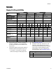
Models Models Reactor 2 H-30 and H-30 Elite H-30 Model Model H-30 Elite Model 10 kW 15 kW 10 kW 15 kW 17H031 17H032 17H131 17H132 Maximum Fluid Working 2000 (14, 140) Pressure psi (MPa, bar) Approximate Output per Cycle 0.073 (0.28) (A+B) gal. (liter) Max Flow Rate lb/min (kg/min) 28 (12.7) 2000 (14, 140) 2000 (14, 140) 2000 (14, 140) 0.073 (0.28) 0.073 (0.28) 0.073 (0.28) 28 (12.7) 28 (12.7) 28 (12.
Models Reactor 2 H-40 and H-40 Elite H-40 Model Model H-40 Elite Model 15 kW 20 kW 15 kW 20 kW 17H043 17H044 17H143 17H144 Maximum Fluid Working 2000 (14, 140) Pressure psi (MPa, bar) Approximate Output per Cycle 0.063 (0.24) (A+B) gal. (liter) Max Flow Rate lb/min (kg/min) 45 (20) 2000 (14, 140) 2000 (14, 140) 2000 (14, 140) 0.063 (0.24) 0.063 (0.24) 0.063 (0.
Models Reactor 2 H-40 and H-40 Elite (Continued) H-40 Model Model H-40 Elite Model 15 kW 20 kW 15 kW 20 kW 17H045 17H046 17H145 17H146 Maximum Fluid Working 2000 (14, 140) Pressure psi (MPa, bar) Approximate Output per Cycle 0.063 (0.24) (A+B) gal. (liter) Max Flow Rate lb/min (kg/min) 45 (20) 2000 (14, 140) 2000 (14, 140) 2000 (14, 140) 0.063 (0.24) 0.063 (0.24) 0.063 (0.
Models Reactor 2 H-50 and H-50 Elite H-50 Model Model H-50 Elite Model 20 kW 20 kW 20 kW 20 kW 17H053 17H056 17H153 17H156 Maximum Fluid Working 2000 (14, 140) Pressure psi (MPa, bar) Approximate Output per Cycle 0.073 (0.28) (A+B) gal. (liter) Max Flow Rate lb/min (kg/min) 52 (24) 2000 (14, 140) 2000 (14, 140) 2000 (14, 140) 0.073 (0.28) 0.073 (0.28 0.073 (0.
Models Reactor 2 H-XP2 and H-XP2 Elite H-XP2 Model Model Proportioner ★ H-XP2 Elite Model 15 kW 15kW 17H062 17H162 Maximum Fluid Working 3500 (24.1, 241) Pressure psi (MPa, bar) Approximate Output per Cycle 0.042 (0.16) (A+B) gal. (liter) Max Flow Rate lb/min (kg/min) 1.5 (5.7) 3500 (24.
Models Reactor 2 H-XP3 and H-XP3 Elite H-XP3 Model Model H-XP3 Elite Model 20 kW 20 kW 20 kW 20 kW 17H074 17H076 17H174 17H176 Maximum Fluid Working 3500 (24.1, 241) Pressure psi (MPa, bar) Approximate Output per Cycle 0.042 (0.16) (A+B) gal. (liter) Max Flow Rate lb/min (kg/min) 2.8 (10.6) 3500 (24.1, 241) 3500 (24.1, 241) 3500 (24.1, 241) 0.042 (0.16) 0.042 (0.16) 0.042 (0.16) 2.8 (10.6) 2.8 (10.6) 2.8 (10.
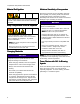
Approvals Approvals Accessories Kit Number Description 24U315 Air Manifold (4 outlets) 17G340 Caster Kit 24T280 Graco InSite Kit 17F837 Inlet Sensor Kit 16X521 Graco InSite Extension cable 24.6 ft (7.5 m) 9902471 24N449 Conforms to ANSI/UL Std. 499 Certified to CAN/CSA Std. C22.2 No.
Supplied Manuals Supplied Manuals Related Manuals The following manuals are shipped with the Reactor 2 . Refer to these manuals for detailed equipment information. The following manuals are for accessories used with the Reactor 2. Manuals are also available at www.graco.com. Component Manuals in English: Manual Description Manuals are available at www.graco.com.
Typical Installation, without circulation Typical Installation, without circulation H J K G A L M K G F (B-RES) N J (A-ISO) D N E S B P C* Figure 1 * Shown exposed for clarity. Wrap with tape during operation.
Typical Installation, with system fluid manifold to drum circulation Typical Installation, with system fluid manifold to drum circulation K H M G A R R L M K G J (B-RES) F J (A-ISO) D E S B P C* Figure 2 * Shown exposed for clarity. Wrap with tape during operation.
Typical Installation, with gun fluid manifold to drum circulation Typical Installation, with gun fluid manifold to drum circulation K H M R G L R J A M K F G (B-RES) N J (A-ISO) E D N S B P C* Figure 3 * Shown exposed for clarity. Wrap with tape during operation.
Component Identification Component Identification D S E P B C* Figure 4 20 334945B
Component Identification Key RR BA BB ISO Side Pressure Relief Outlet RES Side Pressure Relief Outlet CD Advanced Display Module (ADM) EC EM FA FB FH FM Electrical Cord Strain Relief Electric Motor (behind shroud) ISO Side Fluid Manifold Inlet RES Side Fluid Manifold Inlet Fluid Heater (behind shroud) Reactor Fluid Manifold FV Fluid Inlet Valve (RES side shown) GA ISO Side Pressure Gauge XB GB HA RES Side Pressure Gauge ISO Side Hose Connection XF ISO Side PRESSURE RELIEF/SPRAY Valve RES Side
Component Identification Advanced Display Module (ADM) The ADM display shows graphical and text information related to setup and spray operations. Table 1 : ADM Keys and Indicators Key Function Press to startup or shutdown the system. Startup / Shutdown Key and Indicator Press to stop all proportioner processes. This is not a safety or emergency stop. Stop Press to select the specific screen or operation shown on the display directly next to each key.
Component Identification Figure 6 ADM Back View CJ Flat Panel Mount (VESA 100) CK Model and Serial Number CL USB Port and Status LEDs CM CAN Communication Cable Connection CN Module Status LEDs CP Accessory Cable Connection CR CS Token Access Cover Backup Battery Access Cover Table 2 ADM LED Status Descriptions LED Conditions Description System Status Green Solid Run Mode, System On Green Flashing Setup Mode, System On Yellow Solid Run Mode, System Off Yellow Flashing Setup Mode, S
Component Identification ADM Display Details System Errors Power Up Screen The current system error is displayed in the middle of the menu bar. There are four possibilities: The following screen appears when the ADM is powered up. It remains on while the ADM runs through initialization and establishes communication with other modules in the system. Icon No Icon Function No information or no error has occurred Advisory Deviation Alarm See Troubleshoot Errors, page 60 for more information.
Component Identification Icons Icons Icon Softkeys Function Component A Component B Icon Function Start Proportioner Stop Proportioner Turn on or off the specified heat zone. Estimated Supply Material Park pump Hose Temperature Reset Cycle Counter (press and hold) Pressure Select Recipe Cycle Counter (press and hold) Search Advisory. See Troubleshoot Errors, page 60 for more information. Move Cursor Left One Character Deviation. See Troubleshoot Errors, page 60 for more information. Alarm.
Component Identification Electrical Enclosure H-40, H-50, H-XP3 H-30, H-XP2 AAA Temperature Control Module (TCM) AAB Hydraulic Control Module (HCM) AAC Enclosure Fan(s) AAD Wiring Terminal Blocks (H-30/H-XP2 only) AAE Power Supply AAF Sacrificial Surge Protector (SSP) AAG Hose Breaker AAH Motor Breaker AAJ A Side Heat Breaker AAK B Side Heat Breaker AAL Hose Transformer Breaker AAM Motor Contactor AAN TB21 Terminal Block (if equipped) MP Main Power Switch 26 334945B
Component Identification Hydraulic Control Module (HCM) HCM Rotary Switch (RS) Positions 0 = Reactor 2, H-30 1 = Reactor 2, H-40 2 = Reactor 2, H-50 3 = Reactor 2, H-XP2 4 = Reactor 2, H-XP3 Table 3 HCM Module LED (MS) Status Descriptions LED Conditions Description HCM Status Green Solid Power applied to module Yellow Solid Active Communication Red Steady Flashing Software upload from token in progress Red Random Flashing or Solid Module error exists Figure 7 Description MS 1 2 Module Status L
Component Identification Temperature Control Module (TCM) Cable Connections Table 4 TCM Module LED (7) Status Descriptions Figure 8 1 2 3 4 5 6 7 8 9 10 28 Power Input LED Conditions Description TCM Status Green Solid Power applied to module Yellow Solid Active Communication Module Status LEDs Red Steady Flashing Heater A (ISO) Temperature Heater B (RES) Temperature Hose Temperature Software upload from token in progress Red Random Flashing or Solid Module error exists Heater Overtempera
Setup Setup Grounding The equipment must be grounded to reduce the risk of static sparking and electric shock. Electric or static sparking can cause fumes to ignite or explode. Improper grounding can cause electric shock. Grounding provides an escape wire for the electric current. • Reactor: System is grounded through the power cord. • Spray gun: connect whip hose ground wire to FTS. See Install Fluid Temperature Sensor. Do not disconnect ground wire or spray without whip hose.
Setup Connect Power Table 5 Power Cord Requirements NOTE: All electrical wiring must be done by a qualified electrician and comply with all local codes and regulations. Model Input Power Cord Specifications* AWG (mm^2) H-30, 10.2 kW 200-240 VAC, 1 Phase 4 (21.2), 2 wire + ground 200-240 VAC, 3 Phase, DELTA 8 (8.4), 3 wire + ground 350-415 VAC, 3 Phase, WYE 8 (8.4), 4 wire + ground 200-240 VAC, 1 Phase 4 (21.2), 2 wire + ground 200-240 VAC, 3 Phase, DELTA 6 (13.
Setup Lubrication System Setup 5. The lubrication is ready for operation. No priming is required. Component A (ISO) Pump: Fill ISO lube reservoir (LR) with Graco Throat Seal Liquid (TSL), part 206995 (supplied). Install Fluid Temperature Sensor 1. Lift the lubricant reservoir (LR) out of the bracket (RB) and remove the container from the cap. The Fluid Temperature Sensor (FTS) is supplied. Install FTS between main hose and whip hose (see Related Manuals, page 16).
Advanced Display Module (ADM) Operation Advanced Display Module (ADM) Operation When main power is turned on by turning the main power switch (MP) to the ON position, the power up screen will be displayed until communication and initialization is complete. 1. Set pressure values for the Pressure Imbalance Alarm to activate. See System Screen 1, page 36. Then the power key icon screen will display until the ADM power on/off button (A) is pressed for the first time after system power-up.
Advanced Display Module (ADM) Operation Setup Mode The ADM will start in the Run screens at the Home screen. From the Run screens, press to access the Setup screens. The system defaults with no password, entered as 0000. Enter the current password then press . Press Setup Screens Navigation Diagram, page 45. to navigate through the Setup Mode screens. See Set Password Set a password to allow Setup screen access, see Advanced Screen 1 – General, page 35. Enter any number from 0001 to 9999.
Advanced Display Module (ADM) Operation Setup Screens Navigation 34 334945B
Advanced Display Module (ADM) Operation Advanced Setup Screens Advanced setup screens enable users to set units, adjust values, set formats, and view software information for each component. Press desired Advanced setup screen, press complete press to scroll through the Advanced setup screens. Once in the to access the fields and make changes. When changes are to exit edit mode. NOTE: Users must be out of edit mode to scroll through the Advanced setup screens.
Advanced Display Module (ADM) Operation System 1 System 3 Use this screen to set the activation pressure for the Pressure Imbalance Alarm and Deviation, enable or disable diagnostic screens, set the maximum and minimum drum volume, and enable drum alarms. Use this screen to enable alternate pump cylinder sizes, to turn motor standby mode on and off, and to enable recirculation cycle count. Cycles below 700 psi outlet pressure will not be counted unless enabled.
Advanced Display Module (ADM) Operation Recipes Add Recipe Use this screen to add recipes, view saved recipes, and enable or disable saved recipes. Enabled recipes can be selected at the Home Run Screen. 24 recipes can be displayed on the three recipe screens. 1. Press and then use recipe field. Press to select a to enter a recipe name (maximum 16 characters). Press old recipe name. 2. Use to clear the to highlight the next field and use the number pad to enter a value. Press to save.
Advanced Display Module (ADM) Operation Run Mode The ADM will start in the Run screens at the “Home” screen. Press screens. See Run Screens Navigation Diagram, page 44. From the Run screens, press to navigate through the Run Mode to access the Setup screens.
Advanced Display Module (ADM) Operation Home — System Off Home — System With Error This is the home screen when the system is off. This screen displays actual temperatures, actual pressures at the fluid manifold, and number of cycles. Active errors are shown in the status bar. The error code, alarm bell, and description of the error will scroll in the status bar. 1. Press to acknowledge the error. 2. See for corrective action.
Advanced Display Module (ADM) Operation Maintenance Events Use this screen to view daily and lifetime cycles or gallons that have been pumped and gallons or liters remaining in the drums. This screen shows the date, time, event code, and description of all events that have occurred on the system. There are 10 pages, each holding 10 events. The 100 most recent events are shown. See System Events, page 43 for event code descriptions.
Advanced Display Module (ADM) Operation Troubleshooting This screen displays the last ten errors that occurred on the system. Use the up and down arrows to select an error and press QR Codes to view the QR code for the selected error. Press to access the QR code screen for an error code that is not listed on this screen. See Error Codes and Troubleshooting, page 61, for more information on error codes. To quickly view online help for a given error code, scan the displayed QR code with your smartphone.
Advanced Display Module (ADM) Operation Diagnostic Job Data Use this screen to view information for all system components. NOTE: If not visible, this screen may be on the Setup Systems screen (see Setup Mode). Use this screen to enter a job name or number. Recipes The following information is displayed: Use this screen to select an enabled recipe.
Advanced Display Module (ADM) Operation System Events Use the table below to find a description for all system non-error events. All events are logged in the USB log files.
Startup Startup 5. Confirm main power switch is OFF before starting generator. To prevent serious injury, only operate Reactor with all covers and shrouds in place. NOTICE Proper system setup, startup, and shutdown procedures are critical to electrical equipment reliability. The following procedures ensure steady voltage. Failure to follow these procedures will cause voltage fluctuations that can damage electrical equipment and void the warranty. 6.
Startup 9. Switch on the air compressor, air dryer, and breathing air, if included. e. Open fluid inlet valves (FV). Check for leaks. 10. For first startup of new system, load fluid with feed pumps. Cross-contamination can result in cured material in fluid lines which could cause serious injury or damage equipment. To prevent cross-contamination: a. Check that all Setup steps are complete. See Setup, page 29. • Never interchange component A and component B wetted parts. b.
Startup 11. Press to activate ADM. Thermal expansion can cause over-pressurization, resulting in equipment rupture and serious injury, including fluid injection. Do not pressurize system when preheating hose. 12. If necessary, setup the ADM in Setup Mode. See Advanced Display Module (ADM) Operation, page 32. 13. Preheat the system: a. Press to turn on hose heat zone. b. If you need to circulate fluid through the system to preheat the drum supply, see Circulation Through Reactor, page 47.
Fluid Circulation Fluid Circulation Circulation Through Reactor 4. Set temperature targets. See Targets, page 39. 5. Before starting the motor, unlock the hydraulic compensator knob, then rotate counter-clockwise until it ceases to move. NOTICE To prevent equipment damage, do not circulate fluid containing a blowing agent without consulting with your material supplier regarding fluid temperature limits.
Fluid Circulation Circulation Through Gun Manifold NOTICE To prevent equipment damage, do not circulate fluid containing a blowing agent without consulting with your material supplier regarding fluid temperature limits. 2. Route circulation lines back to respective component A or B supply drum. Use hoses rated for the maximum working pressure of this equipment. See Technical Specifications. 3. Follow procedures from Startup, page 44. 4. Turn main power switch on.
Spraying Spraying 6. Open fluid inlet valve (FV) located at each pump inlet. The Fusion AP gun is shown. 1. Engage gun piston safety lock and close gun fluid inlet valves A and B. Fusion Probler 7. Press to start motor and pumps. 2. Attach gun fluid manifold. Connect gun air line. Open air line valve. 3. Adjust the gun air pressure. Do not exceed 130 psi (0.2 MPa, 2 bar). 4. Set PRESSURE RELIEF/SPRAY valves (SA, SB) to SPRAY . GA SA 8.
Spraying 9. Check fluid pressure gauges (GA, GB) to ensure proper pressure balance. If imbalanced, reduce pressure of higher component by slightly turning PRESSURE RELIEF/SPRAY valve for that component toward PRESSURE until gauges show RELIEF/CIRCULATION balanced pressures. GA 11. Disengage gun piston safety lock. Fusion GB SA SB Probler 12. Pull gun trigger to test spray onto cardboard. If necessary, adjust pressure and temperature to get desired results. Spray Adjustments 10.
Spraying Manual Hose Heat Mode If the system produces the T6DH Sensor Error Hose alarm or the T6DT Sensor Error TCM alarm, use manual hose heat mode until the hose RTD cable or FTS temperature sensor can be repaired. 3. Select Enable Manual Hose Mode. NOTE: When manual hose mode is enabled, the manual hose mode advisory EVCH-V will appear. Do not use Manual Hose Mode for extended periods of time. The system performs best when the hose has a valid RTD signal and can operate in temperature control mode.
Spraying 5. Navigate back to the Run Mode Home screen. The hose now displays a current instead of a temperature. NOTE: Until the RTD sensor is repaired, the T6DH sensor error alarm will display each time the system is powered up. 52 Disable Manual Hose Mode 1. Enter Setup Mode and navigate to System 2 Screen and deselect Enable Manual Hose Mode, or repair the hose RTD cable or FTS. 2. Manual hose mode is automatically disabled when the system detects a valid RTD sensor in the hose.
Standby Standby If you stop spraying for a period of time, the unit will enter standby by shutting down the electric motor and hydraulic pump, to reduce equipment wear and minimize heat buildup. The pump icon on the ADM Home screen will flash when in standby. NOTE: The A, B, and Hose heat zones will not shut off during standby. To restart, spray off target for two seconds. The system will sense the pressure drop and the motor will ramp up to full speed in a few seconds.
Shutdown Shutdown NOTICE 6. Turn off the air compressor, air dryer, and breathing air. Proper system setup, startup, and shutdown procedures are critical to electrical equipment reliability. The following procedures ensure steady voltage. Failure to follow these procedures will cause voltage fluctuations that can damage electrical equipment and void the warranty. 1. Press to stop the pumps. 2. Turn off all heat zones. 3. Relieve pressure. See Pressure Relief Procedure, page 55. 7.
Pressure Relief Procedure Pressure Relief Procedure Follow the Pressure Relief Procedure whenever you see this symbol. 4. Close gun fluid inlet valves A and B. 5. Shut off feed pumps and agitator, if used. This equipment stays pressurized until pressure is manually relieved. To help prevent serious injury from pressurized fluid, such as skin injection, splashing fluid and moving parts, follow the Pressure Relief Procedure when you stop spraying and before cleaning, checking, or servicing equipment. 6.
Flushing Flushing To flush entire system, circulate through gun fluid manifold (with manifold removed from gun). To avoid fire and explosion: • Flush equipment only in a well-ventilated area. • Ensure main power is off and heater is cool before flushing. To prevent moisture from reacting with isocyanate, always leave the system filled with a moisture-free plasticizer or oil. Do not use water. Never leave the system dry. See Important Two-Component Material Information.
Maintenance Maintenance Table 6 Frequency of Oil Changes Prior to performing any maintenance procedures, follow Pressure Relief Procedure, page 55. Preventative Maintenance Schedule The operating conditions of your particular system determine how often maintenance is required. Establish a preventive maintenance schedule by recording when and what kind of maintenance is needed, and then determine a regular schedule for checking your system.
Maintenance Gun Check Valve Screens Clean gun check valve screens regularly. See gun manual. Dust Protection Use clean, dry, oil-free compressed air to prevent dust buildup on control modules, fans, and motor (under shield). Vent Holes Keep vent holes on bottom and back of electrical enclosure and sides and back of transformer enclosure open.. Flush Inlet Strainer Screen 1. Close the fluid inlet valve at the pump inlet and shut off the appropriate feed pump.
Maintenance Pump Lubrication System 5. Thread the reservoir onto the cap assembly and place it in the bracket. Check the condition of the ISO pump lubricant daily. Change the lubricant if it becomes a gel, its color darkens, or it becomes diluted with isocyanate. 6. Push the larger diameter supply (ST) tube approximately 1/3 of the way into the reservoir. Gel formation is due to moisture absorption by the pump lubricant.
Errors Errors Troubleshoot Errors To troubleshoot the error: View Errors When an error occurs the error information screen displays the active error code and description. 1. Press the soft key next to “Help With This Error” for help with the active error. The error code, alarm bell, and active errors will scroll in the status bar. For a list of the ten most recent errors see Troubleshooting. Error codes are stored in the error log and displayed on the Error and Troubleshooting screens on the ADM.
Error Codes and Troubleshooting Error Codes and Troubleshooting See system repair manual 334946 or visit http://help.graco.com for causes and solutions to each error code, or call your Graco contact listed on the back page of this manual. USB Data USB Logs Download Procedure NOTE: The ADM can read/write to FAT (File Allocation Table) storage devices. NTFS, used by 32 GB or greater storage devices, is not supported.
Error Codes and Troubleshooting Job Log The following data is stored in this file: The job log file name is 2–JOB.CSV and is stored in the DATAxxxx folder. • Date that material was sprayed • Time — unused column The job log maintains a record of data points based on the USB Log Frequency defined in the Setup screens. The ADM stores the last 237,000 data points for download. See Setup - Advanced Screen 3 — USB, page 35, for information on setting the Download Depth and USB Log Frequency.
Error Codes and Troubleshooting Custom Language File The custom language file name is DISPTEXT.TXT and is stored in the DOWNLOAD folder. A custom language file automatically downloads each time a USB flash drive is inserted into the ADM. If desired, use this file to create a user-defined set of custom language strings to be displayed within the ADM. The system is able to display the following Unicode characters.
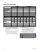
Performance Charts Performance Charts Use this chart to help identify the proportioner that will work most efficiently with each mix chamber. Flow rates are based on a material viscosity of 60 cps. NOTICE To prevent system damage, do not pressurize the system above the line for the gun tip size being used. Foam Performance Chart Table 7 Foam Performance Chart ti26328a 2000 (13.
Performance Charts Coatings Performance Chart Table 8 Coatings Performance Chart ti26345a 3500 (24.1,241) 3000 (20.7,207) 2500 (17.2,172) G 2000 (13.8,138) H PRESSURE psi (MPa, bar) 1500 J (10.3,103) K 1000 KEY G = H-XP2 at 50 Hz H = H-XP2 at 60 Hz J = H-XP3 at 50 Hz K = H-XP3 at 60 Hz (6.9, 69) 500 (3.4, 34) 0 0.5 1.0 1.5 2.0 2.5 3.0 (1.9) (3.8) (5.7) (7.6) (9.5) (11.
Technical Specifications Technical Specifications Reactor 2 Hydraulic Proportioning System Metric U.S. Maximum Fluid Working Pressure for Bare Proportioners Models H-30, H-40, and H-50 2000 psi 13.8 MPa, 138 bar Models H-XP2 and H-XP3 3500 psi 24.1 MPa, 241 bar Fluid: Oil Pressure Ratio Model H-40 1.91 : 1 Models H-30 and H-50 1.64 : 1 Models H-XP2 and H-XP3 2.79 : 1 Fluid Inlets Component A (ISO) 3/4 npt(f), 250 psi maximum 3/4 npt(f), 1.75 MPa, 17.
Technical Specifications Line Voltage Options 230V 1 phase and 230V 3 phase units: 195–264 Vac, 50/60 Hz 400V 3 phase units: 338–457 Vac, 50/60 Hz Amperage Requirement (phase) See the Models listing in the manual. Heater Power (A and B heaters total) See the Models listing in the manual. Hydraulic Reservoir Capacity 3.5 gal. 13.6 liters Recommended Hydraulic Fluid Citgo, A/W Hydraulic Oil, ISO Grade 46 Sound Power, per ISO 9614–2 90.2 dB(A) Sound Pressure 1 m From Equipment 82.
Notes Notes 68 334945B
Dimensions Dimensions 334945B 69
Graco Extended Warranty Graco warrants all equipment referenced in this document which is manufactured by Graco and bearing its name to be free from defects in material and workmanship on the date of sale to the original purchaser for use. Graco will, for a period as defined in the table below from the date of sale, repair or replace any part of the equipment determined by Graco to be defective.