Repair GMAX™ 3400 Airless Sprayers 310813 Rev C Korean patent: 10-0647761 - For Portable Airless Spraying of Architectural Coatings and Paints 3300 psi (22.8 MPa, 228 bar) Maximum Working Pressure Read all warnings and instructions WL D WL D 248663 ✓ 248664 ✓ WL D ✓ 248665 ✓ 248666 ✓ 310802 309639 309250 309640 ✓ WL D Graco Inc. P.O. Box 1441 Minneapolis, MN 55440-1441 Copyright 2005, Graco Inc. is registered to I.S.
Manual Conventions Contents WARNING . . . . . . . . . . . . . . . . . . . . . . . . . . . . . . . . . 3 Maintenance . . . . . . . . . . . . . . . . . . . . . . . . . . . . . . . 5 Troubleshooting . . . . . . . . . . . . . . . . . . . . . . . . . . . . 6 Drive Housing and Connecting Rod . . . . . . . . . . . 8 Pinion Assembly/Clutch Armature/Clamp . . . . . . . 9 Clutch Housing . . . . . . . . . . . . . . . . . . . . . . . . . . . 11 Engine . . . . . . . . . . . . . . . . . . . . . . . . . . . . . . . . . .
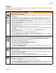
Warning Warning The following warnings include general safety information for this equipment. Further product specific warnings may be included in the text where applicable. WARNING FIRE AND EXPLOSION HAZARD Flammable fumes, such as solvent and paint fumes, in work area can ignite or explode. To help prevent fire and explosion: • Use equipment only in well ventilated area.Do not fill fuel tank while engine is running or hot; shut off engine and let it cool.
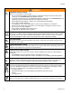
Warning WARNING EQUIPMENT MISUSE HAZARD Misuse can cause death or serious injury. • Do not exceed the maximum working pressure or temperature rating of the lowest rated system component. See Technical Data in all equipment manuals. • Use fluids and solvents that are compatible with equipment wetted parts. See Technical Data in all equipment manuals. Read fluid and solvent manufacturer’s warnings. • Check equipment daily. Repair or replace worn or damaged parts immediately.
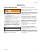
Maintenance Maintenance Pressure Relief Procedure WARNING DAILY: Check gun safety for proper operation. DAILY: Check pressure drain valve for proper operation. DAILY: Check and fill the gas tank. Read Injection Hazard, page 3; Burn Hazard, page 4 1. 2. 3. 4. 5. 6. Lock gun trigger safety. Turn engine ON/OFF switch to OFF. Move pump switch to OFF and turn pressure control knob fully counterclockwise. Unlock trigger safety.
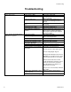
Troubleshooting Troubleshooting Problem Engine will not start Engine operates, but displacement pump does not operate Cause Engine switch is OFF Engine is out of gasoline Solution Turn engine switch ON Refill gas tank. Honda Engines Owner's Manual. Engine oil level is low Try to start engine. Replenish oil, if necessary. Honda Engines Owner's Manual.
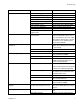
Troubleshooting Problem Pump output is low Cause Solution Strainer (16) is clogged Clean strainer. Piston ball (206) is not seating Service piston ball. Manual 309250. Piston packings are worn or damaged Replace packings. Manual 309250. O-ring (227) in pump is worn or damaged Replace o-ring. Manual 309250. Intake valve ball is not seating properly Clean intake valve. Manual 309250. Intake valve ball is packed with material Clean intake valve. Manual 309250.
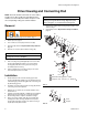
Drive Housing and Connecting Rod Drive Housing and Connecting Rod NOTE: The item numbers referenced are for the Hi-Boy models. The Lo-Boy models may have different item numbers. Use the Hi-Boy item number and part to find the corresponding Lo-Boy part and item number. Removal CAUTION DO NOT use drive housing screws (18) to align or seat bearing housing with drive housing. Align these parts with locating pins, to avoid premature bearing wear. 7. 8. WARNING Install screws (18) in drive housing.
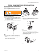
Pinion Assembly/Clutch Armature/Clamp Pinion Assembly/Clutch Armature/Clamp Pinion Assembly/Clutch Armature Removal Pinion Assembly If pinion assembly (50) is not removed from clutch housing (51), do 1. through 3. Otherwise, start at 4. ( ( WARNING Read Injection Hazard, page 3; Burn Hazard, page 4 WL E 1. 2. 3. 4. Relieve pressure, page 5. Remove drive housing; page 8. FIG. 14. Disconnect clutch (A) and clutch (B) connectors from control board. a.
Pinion Assembly/Clutch Armature/Clamp Installation Clutch Armature 1. 2. 3. FIG. 7. Lay two stacks of two dimes on smooth bench surface. Lay armature (38) on two stacks of dimes. Press center of hub down to bench surface. WL D LQ PP GLPHV 4. 5. Install armature (38) on engine drive shaft. Install four screws (35) and lock washers (34) with torque of 125 in-lb. Pinion Assembly 6. Install o-ring (50e). 7. FIG. 5. Tap pinion shaft (50c) in with plastic mallet. 8.
Clutch Housing Clutch Housing Removal 1. 2. 3. 4. Remove clamp. Do Clamp Removal, page 10. FIG. 10. Remove four screws (60) and lock washers (59) which hold clutch housing (51) to engine. Remove screw (64) from under mounting plate (D). Pull off clutch housing (51). Installation 1. 2. 3. FIG. 10. Push on clutch housing (51). Install four capscrews (60) and lock washers (59) and secure clutch housing (51) to engine. Torque to 200 in-lb (22.6 N·m).
Pressure Control Pressure Control On/Off Switch Installation Removal 1. WARNING 2. 3. Install new ON/OFF switch (71) so tabs of switch snap into place on inside of cover. Connect ON/OFF switch connector (B) to PC board. Swing up cover (77) and secure with two screws (91). Read Injection Hazard, page 3; Burn Hazard, page 4 1. 2. 3. 4. Relieve pressure, page 5. FIG. 13. Remove two screws (91) and swing down cover (77). Disconnect ON/OFF switch connector (B) from PC board.
Pressure Control Control Board Removal 6. WARNING • Lead (E) from transducer • Lead (B) from ON/OFF switch • Clutch wires Remove four screws (89) and control board (90). Installation Read Injection Hazard, page 3; Burn Hazard, page 4 1. 2. 3. 4. 5. Relieve pressure, page 5. FIG. 13. Remove two screws (91) and swing down cover (77) Remove strain relief bushing (24a). Disconnect engine and ground wires. Disconnect at control board (90): • Lead (D) from potentiometer 1. 2. 3. 4. 5. FIG. 13.
Displacement Pump Displacement Pump Removal 1. 6. FIG. 16. Loosen jam nut by hitting firmly with a 20 oz hammer. Unscrew pump. Flush pump. WARNING Read Injection Hazard, page 3; Burn Hazard, page 4 2. 3. 4. Relieve pressure, page 5. FIG. 15. Stop pump with piston rod (201) in its lowest position. FIG. 14. Loosen two screws (10) and remove pail hook (9). WL D 10 FIG. 16 Repair 9 WL D See manual 309250 for pump repair instructions FIG. 14 5. FIG. 15. Remove hose (93).
Displacement Pump Installation WARNING If pin works loose, parts could break off and project through the air and result in serious injury or property damage. Make sure pin is properly installed. • • 1. WL D CAUTION Replacement pump comes with an outlet fitting installed. Replace installed fitting with fitting marked “GMAX 3400”. If the pump jam nut loosens during operation, the threads of the bearing housing and drive train will be damaged. Tighten jam nut as specified. WL D WL D Fig.
Parts Parts Parts Drawing - GMAX 3400 Hi-Boy Sprayers '(7$,/ $ 5HI 5HI %RWWRP 9LHZ '(7$,/ $ WL D 5HI )25 3$576 6(( 3$*( 16 6HH SDUWV SDJH 310813 Rev C
Parts Parts List - GMAX 3400 Hi-Boy Sprayers Model 248663 Ref. No. 1 2 3 4 Part No. 108879 110837 110838 246428 5 6 7 8 9 10 11 12 13 14 15 16 17 18 19 34 35 36 37 38 39 40 41 42 43 44 45 46 119789 287053 195150 196762 15C146 117501 115099 15E813 15B652 103413 15E805 246385 276888 119426 287411 105510* 108803 183401 193680 * * * 101682* 112827 192027 108068 183350 245245 310813 Rev C Description Qty. ENGINE, gasoline, 4.
Parts Parts Drawing and List - Pinion Housing Ref No. 50: Pinion Housing No. 50 50a 50b 50c* 50d* Part No.
Parts Notes 310813 Rev C 19
Parts Parts Drawing - GMAX 3400 Lo-Boy Sprayers '(7$,/ $ 5HI 5HI %RWWRP 9LHZ '(7$,/ $ WL D 6a 5HI )25 3$576 6(( 3$*( 20 6HH SDUWV SDJH 310813 Rev C
Parts Parts List - GMAX 3400 Lo-Boy Sprayers Model 248665 Ref No. 1 2 3 4 Part No. 108879 110837 110838 246428 5 6 6a 7 8 9 10 11† 12 14† 15† 16† 17† 18 19 34 35 36 37 38 39 40 41 42 43 44 45 46 119789 287053 196750 195150 196762 15C146 117501 115099 15E813 103413 287416 246385 276888 119426 287411 105510* 108803 183401 193680 * * * 101682* 112827 192027 108068 183350 245245 310813 Rev C Description Qty ENGINE, gasoline, 4.
Pressure Control/Filter Assembly Pressure Control/Filter Assembly GMAX 3400 Sprayers Models 248663 through 248666 &/87&+ $ &/87&+ % $ $ WR (QJLQH E D WL D 22 D E 310813 Rev C
Pressure Control/Filter Assembly Pressure Control/Filter Assembly GMAX 3400 Sprayers Models 248663 through 248666 REF NO. 20 21 22 24 25 26 27 28 29 30 31 58 PART NO.
Complete Sprayers - with RAC X Tip, Gun & Hose Complete Sprayers - with RAC X Tip, Gun & Hose Models 248664, 248666 GMAX 3400 Airless Paint Sprayers Includes items 201 to 204 Ref No. 201 202 203 204 24 Part No. Description Qty 248663 Hi-Boy Sprayer 1 See parts list on page 17 248665 Lo-Boy Sprayer 1 See parts list on page 21 240794 HOSE, grounded, nylon; 1/4 in. ID; 1 cpld 1/4 npsm(fbe); 50 ft (15 m); spring guards both ends 3300 psi (227 bar, 27.7 MPa) 238358 HOSE, grounded, nylon; 3/16 in.
Technical Data Technical Data Honda GX120 Engine ANSI Power Rating @ 3600 rpm 4.0 Horsepower (2.9 kW) 3300 psi (227 bar, 22.7 MPa) Maximum working pressure Noise Level Sound power 100 dBa per ISO 3744 86 dBa measured at 3.1 feet (1 m) 0.75 gpm (2.84 liter/min) 1 gun with 0. 027 in.
Graco Standard Warranty Graco Standard Warranty Graco warrants all equipment referenced in this document which is manufactured by Graco and bearing its name to be free from defects in material and workmanship on the date of sale to the original purchaser for use. With the exception of any special, extended, or limited warranty published by Graco, Graco will, for a period of twelve months from the date of sale, repair or replace any part of the equipment determined by Graco to be defective.