Operation - Repair RS™ Gun and Cutter 3A0232R EN For use with polyester resin and gel-coat. For professional use only. Important Safety Instructions Read all warnings and instructions in this manual. Save these instructions. See page 3 for model information, including maximum working pressure.
Contents Models . . . . . . . . . . . . . . . . . . . . . . . . . . . . . . . . . . . 3 Related Manuals . . . . . . . . . . . . . . . . . . . . . . . . . . . 3 Warnings . . . . . . . . . . . . . . . . . . . . . . . . . . . . . . . . . 4 Important Two-Component Information . . . . . . . . 6 Material Self-ignition . . . . . . . . . . . . . . . . . . . . . 6 Keep Components A and B Separate . . . . . . . . . 6 Changing Materials . . . . . . . . . . . . . . . . . . . . . . .
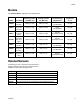
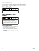
Models Models See Technical Data on page 62 for more specifications. Maximum Fluid Working Pressure psi (MPa, bar) Maximum Catalyst Working Pressure psi (MPa, bar) Air Inlet Working Pressure Range psi (MPa, bar) Maximum Fluid Temperature °F (°C) Model Description 258853 Internal Mix Gel Gun 2000 (14, 138) 2000 (14, 138) 0-125 (0-0.86, 0-8.6) 100 (38) 258854 Internal Mix Chop Gun, No Cutter 2000 (14, 138) 2000 (14, 138) 0-125 (0-0.86, 0-8.
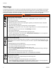
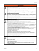
Warnings Warnings The following warnings are for the setup, use, grounding, maintenance, and repair of this equipment. The exclamation point symbol alerts you to a general warning and the hazard symbols refer to procedure-specific risks. When these symbols appear in the body of this manual, refer back to these Warnings. Product-specific hazard symbols and warnings not covered in this section may appear throughout the body of this manual where applicable.
Warnings WARNING TOXIC FLUID OR FUMES HAZARD Toxic fluids or fumes can cause serious injury or death if splashed in the eyes or on skin, inhaled, or swallowed. • Read MSDSs to know the specific hazards of the fluids you are using. • Store hazardous fluid in approved containers, and dispose of it according to applicable guidelines. • Always wear chemically impermeable gloves when spraying, dispensing, or cleaning equipment.
Important Two-Component Information Important Two-Component Information Material Self-ignition Some materials may become self-igniting if applied too thickly. Read material manufacturer’s warnings and material MSDS. Keep Components A and B Separate Cross-contamination can result in cured material in fluid lines which could cause serious injury or damage equipment. To prevent cross-contamination of the equipment’s wetted parts, never interchange component A (catalyst) and component B (resin) parts.
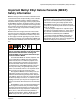
Important Methyl Ethyl Ketone Peroxide (MEKP) Safety Information Important Methyl Ethyl Ketone Peroxide (MEKP) Safety Information MEKP is among the more hazardous materials found in commercial channels. Proper handling of the “unstable (reactive)” chemicals presents a definite challenge to the plastics industry.
Important Methyl Ethyl Ketone Peroxide (MEKP) Safety Information Polyester Resins and Gel-Coats Spraying materials containing polyester resin and gel-coats creates potentially harmful mist, vapors and atomized particulates. Prevent inhalation by providing sufficient ventilation and the use of respirators in the work area. Read the material manufacturer’s warnings and material MSDS to know specific hazards and precautions related to polyester resins and gel-coats.
Important Methyl Ethyl Ketone Peroxide (MEKP) Safety Information 3A0232R 9
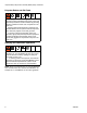
Component Identification Component Identification External Mix Gel Gun, 258840 A B C D E M G F L H K 258840_3A0232_1g J Key: A B C D E F Trigger Clamp Assembly Gun Mount Front Head Locking Ring Air Cap Retaining Ring External Mix Aircap External Mix Front Head G H J K L M Spray Tip Trigger guard Trigger Trigger lock Handle Actuator Pin FIG.
Component Identification Internal Mix Gel Gun, 258853 NOTE: On internal mix guns, the tip rotates to allow a vertical or horizontal spray pattern. B A C D E M G F L K H J ti21003a Key: A B C D E F Trigger Clamp Assembly Gun Mount Front Head Locking Ring Air Cap Retaining Ring Internal Mix Aircap Internal Mix Front Head G H J K L M Spray Tip Trigger guard Trigger Trigger lock Handle Actuator Pin FIG.
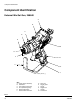
Component Identification Internal Mix Chop Gun, 258854 NOTE: On internal mix guns, the tip rotates to allow vertical or horizontal spray pattern. B A C D E M G L F H K ti21004b J Key: A B C D E F Trigger Clamp Assembly Cutter Mount Front Head Locking Ring Air Cap Retaining Ring Internal Mix Aircap Internal Mix Front Head G H J K L M Spray Tip Trigger guard Trigger Trigger lock Handle Actuator Pin FIG.
Component Identification Internal Mix Chop Gun, 24P436, High Flow, Carbide Seat NOTE: On internal mix guns, the tip rotates to allow vertical or horizontal spray pattern. B A C D E M G L F H K J ti21005b Key: A B C D E F Trigger Clamp Assembly Cutter Mount Front Head Locking Ring Air Cap Retaining Ring Internal Mix Aircap Internal Mix Front Head, High Flow G H J K L M Spray Tip Trigger guard Trigger Trigger lock Handle Actuator Pin FIG.
Component Identification External Mix Chop Gun, 258852 A B C D E G M F L H K J ti21006b Key: A B C D E F Trigger Clamp Assembly Cutter Mount Front Head Locking Ring Air Cap Retaining Ring External Mix Aircap External Mix Front Head G H J K L M Spray Tip Trigger guard Trigger Trigger lock Handle Actuator Pin FIG.
Theory of Operation Theory of Operation Grounding External Mix The resin or gelcoat stream and the catalyst stream impinge when they exit the spray tip. The catalyst is atomized with air pressure by the AAC air to achieve high mix quality. External mixing reduces internal clogs from cured material. This equipment must be grounded. Grounding reduces the risk of static shock by providing an escape wire for electrical current due to static build up or in the event of short circuit.
Setup Setup NOTICE The equipment was tested with lightweight oil, which is left in the fluid passages to protect parts. To avoid contaminating your fluid with oil, flush the equipment with a compatible solvent before using the equipment. See Flush System, page 24. 1. Before first use, flush the gun. See Flush System, page 24. NOTE: The recommended solvent pressure during flushing is 80-100 psi (550-700 kPa, 5.5-7.0 bar). 2. Engage trigger lock. e. Adjust cutter dispensing angle and chute angle as desired.
Setup 10. Adjust AAC pressure on proportioner. 11. Perform test spray. Adjust system and gun settings as necessary to get desired results.
Startup Startup 1. Inspect o-rings on housings. Replace as needed. See FIG. 8. Housing O-rings C D 258840_3A0232_3g FIG. 8 2. Prime the system as required. NOTICE Gun damage can occur when the system is primed with the front head installed. To avoid damage, only prime the system with the front head removed. 3. Align front head with housings and install front head. Tighten front head locking ring (C). 4. Verify air cap retaining ring (D) is tight.
Operation Operation Adjust AAC High-pressure fluid from gun, hose leaks, or ruptured components will pierce skin. This may look like just a cut, but it is a serious injury that can result in amputation. Get immediate surgical treatment. • Do not point gun at anyone or at any part of the body. • Do not put your hand over the dispense outlet. • Do not stop or deflect leaks with your hand, body, glove, or rag.
Pressure Relief Procedure Pressure Relief Procedure 1. Shutdown proportioner. 2. Relieve proportioner pressure. See proportioner manual. 3. Engage gun trigger lock. 4. Close the bleed-type master air valve. 5. Disengage the trigger lock. 6. Hold a metal part of the gun firmly to a grounded metal pail. Trigger the gun to relieve pressure. 7. Engage the trigger lock. 8. With a waste container in place, open all fluid drain valves in the system. Leave drain valve(s) open until you are ready to spray again.
Shutdown Shutdown 4. For internal mix guns, remove mixing element. Daily Shutdown NOTICE Failure to perform this procedure correctly and according to the prescribed schedule can result in poor mixing, fluid leaking, and cured material in or on the gun. ti17896b 1. Perform Pressure Relief Procedure. 5. Remove front head. 2. Solvent flush at 80-100 psi (550-700 kPa, 5.5-7.0 bar) for five seconds. ti17897b 3. Loosen then remove air cap retaining ring.
Shutdown 6. Immerse front head, front cap, and the mixing element (internal mix guns only) in solvent. Use a sealed container to prevent solvent evaporation. 8. Rinse excess resin from the resin port. NOTICE Immersing the cutter assembly in solvent will damage it and void the warranty. ti17900b 9. Lubricate the gun front face and check valve ports with grease (Part No. 118665) as shown in the following illustration.
Shutdown Long-Term Shutdown NOTICE Failure to clean the surface between the trigger clamp and the gun body can lead to material buildup preventing the clamp from seating properly resulting in material leakage from the front of the gun. 10. Wipe the trigger clamp assembly, actuator pins, and surface between the trigger clamp and the gun body with a rag to remove material. Use a compatible solvent. If gun will be unused for at least one week, perform this long-term shutdown procedure. 1.
Maintenance Maintenance Flush System NOTE: • Flush before changing colors, before fluid can dry in the equipment, before storing, and before repairing equipment. Flush at the lowest pressure possible. Check connectors for leaks and tighten as necessary. Flush with a fluid that is compatible with the fluid being dispensed and the equipment wetted parts. • • NOTICE Immersing the cutter assembly in solvent will damage it and void the warranty. 1. Follow Pressure Relief Procedure, page 20. 2.
Troubleshooting Troubleshooting See the troubleshooting procedures beginning on page 29 for additional troubleshooting help. Problem Cause Solution Catalyst leaking Trigger clamp assembly slipped See Fluid Leaking from Front of Gun on page 29.
Troubleshooting Problem Cause Solution Gun does not fully actuate when triggered Trigger clamp not opening properly Perform Adjust Trigger Clamp procedure on page 29 Safety lock engaged Disengage safety lock Trigger clamp pins bent Inspect and replace if necessary Cutter air valve stuck Inspect and replace if necessary Overspray on trigger clamp pins Clean and lubricate Needle assembly stuck Check and adjust needle packing tension, see Adjust Needle Packing Tension on page 30 Hardened mater
Troubleshooting Problem Cause Solution Catalyst is present but no resin No resin Check material fluid level Trigger clamp out of phase 1) Adjust Trigger Clamp, page 29 2) Adjust Actuator Pin Adjustment Screws, page 31 Catalyst pump in bypass Turn on and make ready to spray Actuator adjustment screw missing Replace then perform Adjust Actuator Pin Adjustment Screws, page 31 Trigger worn Inspect and replace if necessary Actuator pin worn Inspect and replace if necessary Trigger clamp assembly
Troubleshooting Problem Cause Solution No solvent Not enough solvent pressure Increase solvent pressure to the recommended range of 80-100 psi (550-700 kPa, 5.5-7.0 bar).
Troubleshooting Fluid Leaking from Front of Gun To prevent skin injection, never use a gun that has a resin and/or catalyst leakage. Adjust Trigger Clamp To prevent skin injection, never use a gun that has a resin and/or catalyst leakage. Perform this procedure to find the source of the leakage and to stop the leak. 1. Perform Adjust Trigger Clamp to attempt to fix the leak. 2. If the leakage still exists: a. Follow Pressure Relief Procedure, page 20. b.
Troubleshooting Fluid Leaking from Under Trigger Clamp Assembly c. 1. Follow Pressure Relief Procedure, page 20. d. Reassemble the needle assembly. 2. Remove trigger clamp assembly (A). e. Install the needle assembly into the gun. A f. Discard the o-ring (909) if wear or damage is found. See Adjust Trigger Clamp on page 29 to install and adjust the trigger clamp. Adjust Needle Packing Tension 3. Tighten packing nut (906).
Troubleshooting Adjust Actuator Pin Adjustment Screws 7. Adjust each screw until the actuator pin just begins to touch the trigger. This can be verified by the trigger just beginning to lift off of the trigger lock. 8. Back each screw out 1/2 turn. 9. Disengage trigger lock. Perform this procedure if the trigger clamp pulls away from the gun body unevenly when the trigger is pulled, see FIG. 12. This procedure adjusts the actuator pins (111) in the trigger clamp, see FIG. 11. 10.
Repair Repair Remove Hardened Material from Internal Mix Front Head 802 801 804 803 805 816* 806* 810 808 812* * Parts shown are not available on internal mix, high flow front heads 813* FIG. 13 Perform this procedure when the internal mix diffuser assembly is filled with cured material. When this happens, the diffuser assembly must be drilled out. 1. Perform Pressure Relief Procedure, page 20. 2. Loosen then remove retaining ring (810) and air cap assembly (808) from head (801). 3.
Repair 7. For standard 1/4 in. mixers, use a 0.152 in. drill in the diffuser assembly outlet to remove hardened material. For high flow 3/8 in. mixers, use a 0.161 in. drill. 12. Install check valve (812) and new spring (813) into the seat then install cap (806). See FIG. 18 for orientation of parts. NOTE: Parts shown are not available on internal mix, high flow front heads Outlet ti17687a FIG. 16 FIG. 14 8. For 1/4 in. mixers, use a 0.246 in.
Repair Replace Internal Mix Element 802 801 804 803 805 816* 806* 810 808 * Parts shown are not available on internal mix, high flow front heads 812* 813* FIG. 17 See internal mix front head parts list on page 50 for available kits. 8. Install check valve (812) and spring (813) into the seat then install cap (806). See FIG. 18 for orientation of parts.
Repair Replace External Mix Check Valve and O-Rings 702 701 717 703 704 718 705 710 706 709 FIG. 19 See Front Head Assemblies beginning on page 49 for available kits. 1. Perform Pressure Relief Procedure, page 20. 2. Remove retaining ring (710) and air cap assembly (709) from head (701). 10. Install air cap onto head and tighten retaining ring (710). NOTICE To prevent distorting the end of the cap (706), do not over-tighten the check valve assembly. 3. Remove check valve assembly (703). 4.
Repair Replace Material Needle Assembly Replace Center Needle Assembly NOTE: The material needle assemblies are the two side needles (105) in the rear of the gun. See page 38. 1. Follow Pressure Relief Procedure, page 20. 1. Follow Pressure Relief Procedure, page 20. 2. Loosen four screws (113) then remove trigger clamp assembly (111). See page 38. 3. Use 1/2 in. deep well socket to break loose and remove material needle assemblies. 2. Loosen four screws (113) then remove trigger clamp assembly (111).
Repair Replace Needle Packing NOTE: The needle packing is the seal (904) inside the needle assembly (105). See pages 38 and 52. NOTICE Needles bend easily. To prevent bending and damaging the needles, be careful when using wrenches to remove the needle packings. 1. Follow Pressure Relief Procedure, page 20. 2. Use 9/64 in. hex key to loosen the four screws (114) on trigger clamp (111). Remove clamp. See page 38. 3. Use 7/16 in. wrench to break loose then remove the packing nuts (906). See page 52. 4.
Parts Parts External Mix Gel Gun, 258840 129 130 131 133 132 128 134 115b 116 113 111 115 139 112 114 141 109 108 107 106 116a 105 160 115a 104 134 143 110 138 153 127 136 101 135 152 103 117 102 121 155 122 159 119 118 123 124 126 120 125 ti21015a 38 3A0232R
Parts Ref 100 101 102†‡ 103‡ Part 199360 24N711 24E428 16C104 24M833 104† 105** 106❄ 107❄ 108❄ 109❄ 110❄ 111◆ 112◆ 113◆ 114◆ 115❖ 24D201 24E417 16C101 123633 16C100 24E429 24E430 16C098 16C099 124057 GC2082 24E423 115a 123934 115b 112319 116❖ 116a 117 118 119 120✿ 121✿ 121a 122✿ 123 124 125 126 127 128* 129* 130* 131* 132* 24E424 112319 24E427 16C705 111316 179737 16C085 16F627 123733 276745 112033 16C130 111945 16C107 16C118 16C117 24E437 24E431 24E432 133* 134* 135 136 138★ 16C119 111450 12373
Parts Internal Mix Gel Gun, 258853 229 When converting an Internal Gel gun to an Internal Chop gun, replace top housing with 24M045.
Parts Ref 200 201 202†‡ 203‡ Part 199360 24N711 24E428 16C104 24M833 204† 205** 206 211◆ 212◆ 213◆ 214◆ 215❖ 24D201 24E417 GC2241 16C098 16C099 124057 GC2082 24G764 215a 123934 215b 112319 216❖ 216a 217❖ 24E424 112319 24H270 217a 123934 217b 112319 218 219 220✿ 221✿ 221a 222✿ 223 224 225 226 227 228* 229* 230* 231* 232* 233* 234* 235 236 24G615 16C705 179737 16C085 16F627 123733 276745 112033 16C130 111945 16C107 16C118 16C117 24E437 24E431 24E432 16C119 111450 123737 116134 3A0232R Descri
Parts External Mix Chop Gun with Cutter, 258970 Ref 301 302 303 Part 258852 24E512 16P320 Description GUN, external mix, chop CUTTER ASSEMBLY, external mix LABEL, quick start, RS gun Qty 1 1 1 Internal Mix Chop Gun with Cutter, 258971 Ref 401 402 303 Part 258854 24P681 16P320 Description GUN, internal mix, chop CUTTER ASSEMBLY, internal mix LABEL, quick start, RS gun Qty 1 1 1 Internal Mix, High Flow, Chop Gun with Cutter, 24P435 Ref 501 402 303 Part 24P436 24P681 16P320 Description GUN, internal
Parts Chop Guns External Mix Chop Gun, 258852 558 530 531 529 541 559 532 542 513 528 511 533 540 512 509 534 516a 543 514 539 545 508 505 546 507 567 538 527 506 515b 515 534 504 502 549 516a1 536 515a 501 563 520 535 503 502 560 510 564 517 522 563 561 524 518 523 548 521 526 525 ti17943b 3A0232R 43
Parts Internal Mix Chop Gun, 258854 563 558 529 541 542 530 531 533 559 532 513 528 543 511 534 512 540 546 539 514 567 509 505 516a 534 516a1 508 538 507 506 515b 515 545 515a 504 502 549 537 527 536 501 535 503 510 564 516b2 560 516b 516b1 502 522 517 561 548 524 563 518 523 526 520 521 525 ti21018a 44 3A0232R
Parts High Flow Internal Mix Chop Gun, 24P436 563 558 529 542 530 531 533 541 559 532 528 513 511 534 540 543 546 512 539 514 516a1 515b 515 515a 534 509 505 516a 508 567 538 545 507 506 504 502 516b 537 527 516b1 549 536 535 564 516b2 501 503 502 510 560 522 517 524 561 548 563 518 523 526 525 520 521 ti21019a 3A0232R 45
Parts External Mix, Internal Mix, and Internal Mix High Flow Chop Gun Parts Quantity Ref Part Description 258852 500 199360 258854 24P436 DOCUMENT, declaration 1 1 501 1 24N711 HANDLE, gun 1 1 1 502†‡ 24E428 SEAL, needle, seat (pack of 6) 2 2 2 503 16C104‡ RETAINER, seat, needle valve, resin 1 1 24M833 RETAINER, seat, needle valve, resin, carbide 505** 24E417 NEEDLE, assembly 2 2 2 506 ❄ 16C101 NEEDLE, aac 1 1 1 507❄ 123633 SPRING, needle assembly 1 1 1 508❄
Parts Quantity Ref Part Description 258852 539◆ 16C103 258854 24P436 BODY, chopper mount 1 1 540◆ 1 16C120 ADAPTER, chopper rotation 1 1 541◆ 1 16F501 TUBE, air pivot 1 24F997 TUBE, air pivot 1 1 542◆ 24E433 PACKING, o-ring (pack of 6) 1 1 1 543◆ 123909 SCREW, cap, socket head 2 2 2 544 239663 SWIVEL, straight 1 1 1 545◆ 124397 SPRING, belleville 1 1 1 546◆ C19080 SCREW, cap, hex head 1 1 1 548 124058 SPRING, compression 1 1 1 549 124282 SCREW
Parts Cutter Adapter Kits External Mix Cutter Adapter Kit, 24E422 ★ Internal Mix Cutter Adapter Kit, 24G832 Internal Mix Adapter External Mix Adapter ti21020a These kits provide replacement parts for the cutter adapter. To convert an external mix gel gun to an external mix chop gun, see External Mix Gel Gun to Chop Gun Conversion on page 55. The internal mix gel gun cannot be converted to a chop gun.
Parts Front Head Assemblies External Mix Horizontal Spray Pattern Front Head, 24E426 External Mix Vertical Spray Pattern Front Head, 24E427 702 701 708 708a 705 706 708a 713 709 712 710 711 717 703 704 718 Ref 701 702 703* 704*† 705*† 706* 708 Part Description Qty 1 262696 HEAD, spray, external mix 16C220 RING, locking 1 1 16C489 SEAL, tip, external mix 1 M72843 BALL, sst 1 123743 SPRING, compression 1 16C490 CAP, check valve, external mix INSERT, valve assist, asm, ext 1 262697 mix 708a 111504 O-RI
Parts Internal Mix Gel Front Head, 24G615 Internal Mix Chop Front Head, 24E442 NOTICE There is a half-moon pin pressed into the front head (801) behind the diffuser assembly (803). Do not attempt to remove this pin. Removal will result in poor mixing.
Parts Internal Mix, High Flow Chop Front Head, 24P562 NOTICE There is a half-moon pin pressed into the front head (801) behind the diffuser assembly (803). Do not attempt to remove this pin. Removal will result in poor mixing. 802 801 803 811 808 804 809 810 805 Ref 801 802 803 804 805 808❄ ★ Part 262703 16C220 16G806 113746 20310-90 262701 262702 809✿❄★ 15G998 810✿❄★ 16E376 811✿❄★ 107313 3A0232R ✿ Parts included in retaining ring kit 24H274.
Parts Needle Assembly, 24E417 906 901 907 905 904 903 902 909 908 ti16592a Beveled edge must face rear of needle Ref 901 902 903* 904* 905* 906 907* 908 909* * 52 Part 123634 16C080 16C081 24H279 16C083 16C086 16C087 24C780 24H281 Description SPRING, needle assembly HOUSING, needle packing RETAINER, packing PACKING, disk (pack of 6) RETAINER, packing NUT, packing material CLIP, retainer NEEDLE, assembly O-RING (pack of 6) Qty 1 1 1 1 1 1 1 1 1 Parts included in needle repair kit 24E418.
Parts O-ring Identification The following illustration shows all available o-rings at actual size. See the respective illustration in the Parts section beginning on page 38 for part references and locations.
Accessories Accessories Fusion® Grease Universal Adapter Kit, 257754 118665, 4 oz. (113 gram) Allows the flexibility to mount an RS gun in place of a variety of guns, including competitor guns. High adhesion, water resistant, lithium-based lubricant. Use this to lubricate the gun. MSDS sheets available at www.graco.com. INDy or Formula Adapter Kit, 125797 Ideal for mounting an RS gun in place of an INDy or Formula gun.
Accessories AAC Regulators External Mix Gel Gun to Chop Gun Conversion 24G571 - for use with internal mix gel guns 22632-00 - for use with internal mix chop guns To convert your external mix gel gun to a chop gun, purchase and install the following kits: 1001 • • • 1005 External Mix Cutter Adapter Kit, 24E422 Trigger Air Valve Kit, 24E425 Cutter Assembly, 24E512 To complete the conversion from an external mix gel gun to a chop gun, remove catalyst restrictor (153) from gun.
Accessories Pressure Fed Roller Adapter Kit, 16T708 Ideal for pressure feed rolling with the RS gun. Application Specific: Part 232122 244163 244164 Description EXTENSION, roller, fixed (0.
Accessories 3A0232R 57
Accessories Impingement (Chop) Spray Tips Pattern Width◆ Increases Flow Increases 58 6 in. (15 cm) 8 in. (20 cm) 10 in. (25 cm) 12 in. (30 cm) 14 in. (36 cm) 16 in. (41 cm) 18 in.
Accessories RS Gun Impingement Spray Tip Part No. † CSTS63 Angled Hole Diameter Straight Hole Diameter Pattern Width ◆ GlasCraft® Tip Part No. Ref 0.036 (0.91) 0.025 (0.64) 12 (300) 23005-J3 CSTS64 0.042 (1.07) 0.029 (0.74) 12 (300) 23005-J4 CSTS65 0.052 (1.32) 0.036 (0.91) 12 (300) 23005-J5 CSTS66 0.062 (1.57) 0.043 (1.09) 12 (300) 23005-J6 CSTS67 0.070 (1.78) 0.052 (1.32) 12 (300) 23005-J7 CSTS71 0.018 (0.46) 0.012 (0.30) 14 (350) 23005-K1 CSTS72 0.021 (0.53) 0.014 (0.
Accessories Airless (Gel) Spray Tips Pattern Width◆ Increases Flow Increases 60 4 in. (10 cm) 6 in. (15 cm) 8 in. (20 cm) 10 in. (25 cm) 12 in.
Accessories RS Gun Airless Spray Tip Part No. † Orifice Diameter Pattern Width ◆ GlasCraft Tip Part No. Ref CST421 CST423 CST427 CST431 CST435 CST443 CST451 CST461 CST471 CST515 CST517 CST519 CST521 CST523 CST527 CST531 CST535 CST543 CST551 CST561 CST571 CST615 CST617 CST619 CST621 CST623 CST627 CST631 CST635 CST643 CST651 CST661 CST671 0.021 (0.53) 0.023 (0.58) 0.027 (0.69) 0.031 (0.79) 0.035 (0.89) 0.043 (1.09) 0.051 (1.30) 0.061 (1.55) 0.071 (1.80) 0.015 (0.38) 0.017 (0.43) 0.019 (0.48) 0.021 (0.
Technical Data Technical Data See Models on page 3 for more information. RS Gun and Cutter US Metric 2000 psi 2000 psi 2000 psi 2000 psi 138 bar, 14 MPa 138 bar, 14 MPa 138 bar, 14 MPa 138 bar, 14 MPa 2000 psi 2000 psi 2000 psi 138 bar, 14 MPa 138 bar, 14 MPa 138 bar, 14 MPa 2000 psi 2000 psi 2000 psi 2000 psi 200 psi 200 psi 200 psi 138 bar, 14 MPa 138 bar, 14 MPa 138 bar, 14 MPa 138 bar, 14 MPa 14 bar, 1.4 MPa 14 bar, 1.4 MPa 14 bar, 1.
Technical Data RS Gun and Cutter Weight 258853 258854 258840 258852 Sound Power Measured per ISO-3746 258853 258854 258840 Sound Pressure Measured at 3 ft (1 m) from equipment. 258853 258854 258840 Wetted Parts Materials of Construction Maximum Air Pressure Maximum Fluid Temperature 3A0232R US Metric 2.32 lb 2.46 lb 2.08 lb 2.33 lb 1.05 kg 1.12 kg 0.94 kg 1.04 kg 98.1 dB (A) at 60 psig 90.6 dB(A) at 50 psig 90.8 dB(A) at 50 psig 80.3 dB (A) at 60 psig 72.8 dB(A) at 50 psig 73.
Technical Data Dimensions C A B 258840_3A0232_1g Dimensions; in. (mm) 64 External, Gel Internal, Gel Internal, Chop External, Chop A, Height 7.37 (187) 7.37 (187) 10.29 (261.4) 10.29 (261.4) B, Length 7.60 (193) 9.2 (234) 9.2 (234) 7.60 (193) C, Width 2.36 (59.9) 2.36 (59.9) 5.07 (129) 5.
Technical Data 3A0232R 65
Graco Standard Warranty Graco warrants all equipment referenced in this document which is manufactured by Graco and bearing its name to be free from defects in material and workmanship on the date of sale to the original purchaser for use. With the exception of any special, extended, or limited warranty published by Graco, Graco will, for a period of twelve months from the date of sale, repair or replace any part of the equipment determined by Graco to be defective.