
User's Manual

Troubleshooting
3A0232R 31
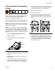
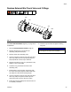
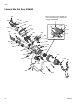
Adjust Actuator Pin Adjustment
Screws
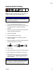
Perform this procedure if the trigger clamp pulls away
from the gun body unevenly when the trigger is pulled,
see F
IG. 12. This procedure adjusts the actuator
pins (111) in the trigger clamp, see F
IG. 11.
When the trigger is pulled, it moves the trigger clamp
assembly resulting in fluid flow from each component.
NOTE: The actuator pins are factory set. If the trigger,
trigger clamp assembly, or pins are removed the trigger
may need to be adjusted.
NOTE: When installing the four finger trigger (16F627),
ensure trigger lock functions and clamp assembly opens
correctly, see F
IG. 12. If any adjustments are needed
perform this Adjust Actuator Pin Adjustment Screws
procedure.
1. Perform Pressure Relief Procedure, page 20.
2. Engage trigger lock.
3. Use 5/64 in. allen key to remove adjustment
screws (114).
4. Apply medium strength thread sealant to threads of
screws.
5. Install adjustment screws (114) into trigger clamp
assembly (111).
6. Squeeze trigger so that it touches the trigger lock. If
trigger cannot touch trigger lock, back out adjust-
ment screws until trigger touches the trigger lock.
7. Adjust each screw until the actuator pin just begins
to touch the trigger. This can be verified by the trig-
ger just beginning to lift off of the trigger lock.
8. Back each screw out 1/2 turn.
9. Disengage trigger lock.
10. While watching the trigger clamp assembly, trigger
the gun to verify both sides of the trigger clamp
assembly pull away from the gun body at the same
time.
11. Hold the trigger fully engaged and measure the
space between the trigger clamp and the gun body
on both sides. The gaps should be at least 0.065 in.
(1.65 mm) in the open position. Adjust screws as
necessary. See F
IG. 12.
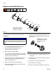
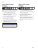
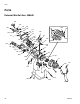
FIG. 11
114
111
F
IG. 12
Even
Good
Uneven
Bad