
User's Manual

Repair
3A0232R 33
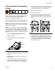
7. For standard 1/4 in. mixers, use a 0.152 in. drill in
the diffuser assembly outlet to remove hardened
material.
For high flow 3/8 in. mixers, use a 0.161 in. drill.
8. For 1/4 in. mixers, use a 0.246 in. drill in the diffuser
assembly inlet to remove hardened material.
For 3/8 in. mixers, use a 0.359 in. drill.
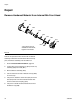
9. Use a pick to remove any cured material from the
front air cap (808).
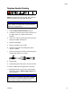
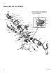
10. Install new mix element into diffuser (803).
11. Install new check valve seat (816) into diffuser. See
F
IG. 16 for seat orientation.
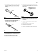
12. Install check valve (812) and new spring (813) into
the seat then install cap (806). See F
IG. 18 for orien-
tation of parts.
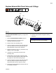
13. Remove and inspect o-ring (804). Replace if worn
or damaged.
14. Lubricate o-ring and install onto diffuser. Install dif-
fuser into head.
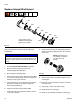
15. Torque cap to 23-27 in-lb (2.6-3.1 N•m).
16. Install diffuser into head (801).
17. Install air cap assembly and tighten retaining ring.
F
IG. 14
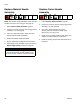
F
IG. 15
ti17687a
Outlet
ti17688a
Inlet
FIG. 16
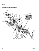
NOTE: Parts shown are
not available on internal
mix, high flow front
heads