
User's Manual

Repair
34 3A0232R
Replace Internal Mix Element
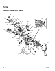
See internal mix front head parts list on page 50 for
available kits.
1. Perform Pressure Relief Procedure, page 20.
2. Remove retaining ring (810) and air cap
assembly (808) from head (801).
3. Remove diffuser assembly (803).
4. Use two wrenches on flats of diffuser and cap (806)
to remove cap. Spring (813) and check valve (812)
will fall out when cap is removed.
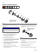
5. Use a small hex key in the small hole in the back of
the diffuser to push the mix element (805) and
check valve seat (816) out.
6. Install new mix element into diffuser (803).
7. Install check valve seat (816) into diffuser. See F
IG.
17 for seat orientation.
8. Install check valve (812) and spring (813) into the
seat then install cap (806). See F
IG. 18 for orienta-
tion of parts.
9. Remove and inspect o-ring (804). Replace if worn
or damaged.
10. Lubricate o-ring and install onto diffuser. Install dif-
fuser into head.
11. Torque cap to 23-27 in-lb (2.6-3.1 N•m).
12. Install diffuser into head (801).
13. Install air cap assembly and tighten retaining ring.
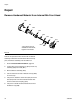
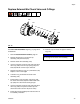
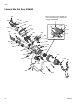
FIG. 17
802
801
804
803
805
810
808
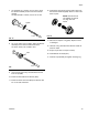
816*
806*
813*
812*
* Parts shown are not
available on internal mix,
high flow front heads
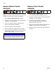
NOTICE
There is a half-moon pin pressed into the front
head (801) behind the diffuser assembly (803). Do not
attempt to remove this pin. Removal will result in poor
mixing.
FIG. 18
NOTE: Parts shown are
not available on internal
mix, high flow front
heads