Instructions-Parts Heated Hoses and Applicator Kits 3A0237L For use with Graco® HFR™ Metering Systems. Not approved for use in European explosive atmospheres. For professional use only. See page 2 for Maximum Fluid Working Pressures and approvals. 130 psi (0.9 MPa, 9 bar) Maximum Air Working Pressure 180°F (82°C) Maximum Hose Operating Temperature Important Safety Instructions Read all warnings and instructions in this manual. Save these instructions.
Related Manuals Contents Related Manuals . . . . . . . . . . . . . . . . . . . . . . . . . . . 2 Heated Hose Bundle Part Numbers . . . . . . . . . . . . 3 Fluid Temperature Sensor (FTS) . . . . . . . . . . . . . 4 Heated Whip Hose . . . . . . . . . . . . . . . . . . . . . . . 4 Individual Hoses . . . . . . . . . . . . . . . . . . . . . . . . . . . 5 Applicator Kits . . . . . . . . . . . . . . . . . . . . . . . . . . . . . 9 MD2 Valve Applicator Kits . . . . . . . . . . . . . . . . . 10 Warnings . . . . . .
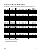
Heated Hose Bundle Part Numbers Heated Hose Bundle Part Numbers Each hose contains an A component hose, a B component hose, and an air hose (1/4 npt x 1/4 npsm, m x f). Part No. Ratio ID in. (mm) Length ft (m) Single Hose Part No.
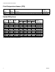
Heated Hose Bundle Part Numbers Fluid Temperature Sensor (FTS) Part No. Fittings Description Maximum Fluid Pressure psi (MPa, bar) 258756 258758 JIC to JIC JIC to JIC Fluid Temperature Sensors for dual heat zones with stainless steel fittings Fluid Temperature Sensors for single heat zone with stainless steel fittings 5000 (34.5, 345) 5000 (34.5, 345) Heated Whip Hose Single Hose Part No. JIC Fittings Part No. ID in.
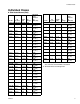
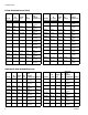
Individual Hoses Individual Hoses A Side Heated Hoses (Red) Part No. ID in. (mm) Length ft (m) JIC Fittings Carbon Steel Heated Dual Heat Zone 24E901 1/4 (6) 5 (1.5) 5/5 24E903 1/4 (6) 10 (3) 5/5 24E905 1/4 (6) 25 (7.6) 5/5 24E907 1/4 (6) 50 (15.2) 5/5 24E909 3/8 (10) 5 (1.5) 5/5 24E911 3/8 (10) 10 (3) 5/5 24E913 3/8 (10) 25 (7.6) 5/5 24E915 3/8 (10) 50 (15.2) 5/5 24E917 1/2 (13) 5 (1.5) 5/5 24E919 1/2 (13) 10 (3) 5/5 24E921 1/2 (13) 25 (7.
Individual Hoses A Side Unheated Hoses (Red) Part No. ID in. (mm) Length ft (m) JIC Fittings Carbon Steel Unheated 262173 1/4 (6) 5 (1.5) 5/5 262175 1/4 (6) 10 (3) 5/5 262177 1/4 (6) 25 (7.6) 5/5 262179 1/4 (6) 50 (15.2) 5/5 262181 3/8 (10) 5 (1.5) 5/5 262183 3/8 (10) 10 (3) 5/5 262185 3/8 (10) 25 (7.6) 5/5 262187 3/8 (10) 50 (15.2) 5/5 262189 1/2 (13) 5 (1.5) 8/8 262191 1/2 (13) 10 (3) 8/8 262193 1/2 (13) 25 (7.6) 8/8 262195 1/2 (13) 50 (15.
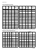
Individual Hoses B Side Heated Hoses (Blue) Part No. ID in. (mm) Length ft (m) JIC Fittings Carbon Steel Heated Dual Heat Zone 24E902 1/4 (6) 5 (1.5) 6/6 24E904 1/4 (6) 10 (3) 6/6 24E906 1/4 (6) 25 (7.6) 6/6 24E908 1/4 (6) 50 (15.2) 6/6 24E910 3/8 (10) 5 (1.5) 6/6 24E912 3/8 (10) 10 (3) 6/6 24E914 3/8 (10) 25 (7.6) 6/6 24E916 3/8 (10) 50 (15.2) 6/6 24E918 1/2 (13) 5 (1.5) 6/6 24E920 1/2 (13) 10 (3) 6/6 24E922 1/2 (13) 25 (7.6) 6/6 24E924 1/2 (13) 50 (15.
Individual Hoses B Side Unheated Hoses (Blue) Part No. ID in. (mm) Length ft (m) JIC Fittings Carbon Steel Unheated 262174 1/4 (6) 5 (1.5) 6/6 262176 1/4 (6) 10 (3) 6/6 262178 1/4 (6) 25 (7.6) 6/6 262180 1/4 (6) 50 (15.2) 6/6 262182 3/8 (10) 5 (1.5) 6/6 262184 3/8 (10) 10 (3) 6/6 262186 3/8 (10) 25 (7.6) 6/6 262188 3/8 (10) 50 (15.2) 6/6 262190 1/2 (13) 5 (1.5) 10/10 262192 1/2 (13) 10 (3) 10/10 262194 1/2 (13) 25 (7.6) 10/10 262196 1/2 (13) 50 (15.
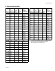
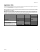
Applicator Kits Applicator Kits The table below lists applicators that can be used with the heated hoses and identifies which applicators require solenoid kits. See Related Manuals for the applicator manual numbers. NOTE: The MD2 valves must use one of the chemical connection kits to connect to the fluid hoses. See MD2 Valve Applicator Kits on page 10.
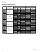
Applicator Kits MD2 Valve Applicator Kits MD2 Handle Part No.
Warnings Warnings The following warnings are for the setup, use, grounding, maintenance, and repair of this equipment. The exclamation point symbol alerts you to a general warning and the hazard symbol refers to procedure-specific risk. Refer back to these warnings. Additional, product-specific warnings may be found throughout the body of this manual where applicable. WARNING ELECTRIC SHOCK HAZARD The hoses must be grounded. Improper grounding, set-up or usage of the hoses can cause electric shock.
Warnings WARNING TOXIC FLUID OR FUMES HAZARD Toxic fluids or fumes can cause serious injury or death if splashed in the eyes or on skin, inhaled, or swallowed. • Read MSDSs to know the specific hazards of the fluids you are using. • Store hazardous fluid in approved containers, and dispose of it according to applicable guidelines. • Always wear chemically impermeable gloves when spraying, dispensing, or cleaning equipment.
Warnings WARNING PERSONAL PROTECTIVE EQUIPMENT You must wear appropriate protective equipment when operating, servicing, or when in the operating area of the equipment to help protect you from serious injury, including eye injury, hearing loss, inhalation of toxic fumes, and burns. This equipment includes but is not limited to: • Protective eyewear, and hearing protection. • Respirators, protective clothing, and gloves as recommended by the fluid and solvent manufacturer.
Important Two-Component Material Information Important Two-Component Material Information Isocyanate Conditions Spraying or dispensing materials containing isocyanates creates potentially harmful mists, vapors, and atomized particulates. Read material manufacturer’s warnings and material MSDS to know specific hazards and precautions related to isocyanates. Prevent inhalation of isocyanate mists, vapors, and atomized particulates by providing sufficient ventilation in the work area.
A and B Components Changing Materials • When changing materials, flush the equipment multiple times to ensure it is thoroughly clean. • Always clean the fluid inlet strainers after flushing. • Check with your material manufacturer for chemical compatibility. • Most materials use ISO on the A side, but some use ISO on the B side. • Epoxies often have amines on the B (hardener) side. Polyureas often have amines on the B (resin) side.
Installation Installation Description Tighten The heated hose maintains proper fluid temperature while dispensing. Fluid hoses are marked with red tape for ISO/hardener/minor volume side, blue tape for RES/resin/major volume side. Fittings have different sized threads to prevent incorrect connection, which can cause fluid crossover and permanently damage the hose. Tighten Hoses are 5 ft (1.5 m), 10 ft (3 m), 25 ft (7.6 m), and 50 ft (15.2 m) long. The whip hose is 5 ft (1.5 m) or 10 ft (3 m) long.
Installation Connect Heated Hoses 4. Connect air hoses (C). Single Heat Zone with A and B Heated Hose D 1. Lay heated hoses end to end, matching the color coding. Red for component A (ISO), blue for component B (RES). C B TI14733a Dual Heat Zone with A and B Heated Hose D A C TI14731a TI15097a D Single Heat Zone with A or B Heated Hose FIG. 3 D 2. Connect fluid hoses (A, B). 3. Connect signal cables (13). B C D TI15140a FIG. 5 5. Connect electrical wires (D). A 13 TI14732a a.
Installation NOTE: Be careful not to cut or nick copper strands. If more than five strands are cut or nicked, trim wire and re-strip. a. Insert one wire from heated hose into connector. Ensure that ferrule is mating with connector insert. See FIG. 9. New hoses are pre-stripped at correct length; remove insulation to expose bare wire. a. Ensure strip length is correct by fitting ferrule over exposed wire. Ferrule should be flush with wire end. See FIG. 7.
Installation f. Insert cap plugs over setscrews. See FIG. 11. Cap plugs Setscrews TI9771A FIG. 11 g. Wrap connector and wire on each side of connector in black electrical tape to help seal out moisture. Ensure 1 in. (25.4 mm) of wire on each side of connector is wrapped. 7. Connect cables (F). Leave slack (G) in cables as stress relief to prevent cable failure. G F TI14734a FIG. 12 8. Repeat for additional hoses. 9. See Connect FTS and Heated Whip Hose, page 20.
Installation Connect FTS and Heated Whip Hose 3. Connect whip hose ground wire (K) to ground screw on underside of FTS. NOTICE To prevent damage to probe, do not kink or excessively bend hose. Do not coil hose tighter than the minimum bend radius of 3 ft (0.9 m). Do not subject hose to excessive weight, impact, or other abuse. 4. Connect fluid hoses to FTS (J). 1. For Single Zone Heat: Carefully extend FTS probe (H) into the hose section from the proportioner. Do not bend or kink probe.
Installation Connect Solenoid Kit 6. Install plug (203), or tube fitting (214) and ball valve (213) in the other side of the tee fitting (202). A solenoid kit is required for some applicators used with Graco Metering Systems. See Individual Hoses on page 5 to see which applicators require a solenoid kit. NOTE: To ensure proper operation of valve, install the solenoid kit within 15 ft (4.5 m) of the applicator. The solenoid reaction time decreases if the solenoid kit is farther away from the applicator.
Installation 4. For 24C757: Connect valve (201) to the B side pump guard (GD) with screws (208) and washers (209). To use 1/2 in. (13 mm) ID fluid hoses, remove the adapters from the proportioner fluid manifold and install them in the FTS swivel inlets. M GD N 206 P TI14737b 209 208 201 r_24c352_3A0237_2a FIG. 17 5. Remove motor cover and connect solenoid cable (206) to cable (2B). 2B FIG. 18 2. For spray guns, close fluid valves on gun fluid manifold. Remove manifold from gun, see gun manual.
Operation Operation Single Heat Zone Shown M Do not operate a coiled hose. A coiled hose creates uneven heat buildup which can result in hose rupture and cause serious injury, including fluid injection. Maximum hose operating temperature is 180°F (82°C). If using hose without an FTS, measure hose temperature to ensure it does not exceed 180°F (82°C). F 13 D Hose must be properly supported to avoid excessive strain due to weight, bending, or sharp edges.
Maintenance Maintenance Clean Orifice Only for MD2 Valve using Orifice Block Kit 24E505 and an orifice. 1. Before disconnecting or repairing hoses, relieve all fluid pressure and shut off electrical power to proportioner. See system operation manual. NOTE: 24E505 does not come with an orifice. See on page 39 for orifice part numbers. 2. Be sure fluid is cool before disconnecting hoses. 1. Follow Pressure Relief Procedure in MD2 valve manual. Instructions for Replacing Individual A or B Hose 1.
Maintenance 3A0237L 25
Maintenance Bundle Individual Whip Hoses 5. Apply scuff guard (10) on each individual material hose up to the electrical connector (5). Individual whip hoses must be bundled with scuff guards and air and signal cables. Follow the instructions below to bundle single and dual heat zone whip hose bundles. 6. Use red electrical tape (12) to secure the scuff guard (10) on the red material hose. See FIG. 21 on page 27. 7.
Maintenance Dual Heat Zone Heated Whip Hose Bundle 5 8 female fittings 8 13 10 2 male fittings B Side 3 female connector 4 A Side male connector 6 in. (152.4 mm) 5 4 1 12 10 16 in. (406.4 mm) 24 in. (609.6 mm) 10 in. (254 mm) 27 in. (685.8 mm) Single Heat Zone Heated Whip Hose Bundle female fittings 8 4 10 8 10 2 male fittings 13 B Side 3 female connector 4 male connector 5 10 A Side 12 1 FIG.
Maintenance Bundle Individual Heated Hoses 7. Use electrical tape and temporarily tape the hose and cable ends together. Individual hoses must be bundled with a scuff guard, FTS cable(s), and air and signal cables.Follow the instructions below to bundle individual heated hoses for dual and single zone heat. 8. Feed the scuff guard (26) over the female material hose fittings. See FIG. 22 on page 29. 1. Lay out the A and B material hoses with the male fittings at the same end of the bundle. 2.
Maintenance Dual Heat Zone Heated Hose Bundle Shown male connectors female connectors 26 29 28 29 4 in. 101.6 mm) male fittings female fittings 1 1 in. (25.4 mm) 18 in. 457.2 mm) 3 in. (76.2 mm) 10 in. (254 mm) 19 in. (482.6 mm) Machine End 2 in. 50.8 mm) 25 32 21 23 21 32 23 A Side A Side 25 25 B Side 33 25 B Side 22 24 22 24 33 1 No exposed foam permitted. FIG.
Parts Parts Whip Hoses NOTE: A FTS assembly must connect the heated hose and whip hose. See page 35.
Parts Heated Whip Hoses Ref. No. 12‡ 13‡ Common Parts Ref. No. 4★ Part No. Description Qty. SCUFF GUARD; 1.75 in. dia.; see 1 varied parts table for length 7▲✖ 15B679 LABEL, safety; A hose, B Hose, 3 and whip hose, English ▲✖ 16M219 LABEL, safety; A hose, B Hose, 3 and whip hose, Spanish/French 8‡ TAPE, electrical; black 1 9 120542 BAG, polyethylene; not shown 2 10✿ SCUFF GUARD; 1.25 in. dia.; see 2 varied parts table for length Part No. Description TAPE, electrical; red TAPE, electrical; blue Qty.
Parts Heated Hose Bundles NOTE: A FTS assembly must connect the heated hose and whip hose. See page 35. Dual Heat Zone Heated Hose Bundle Shown male connectors female connectors 26 29 28 female fittings 29 male fittings Machine End 2 in. 50.
Parts Dual Zone Heated Hose Bundles Common Parts ▲ Replacement Danger and Warning labels, tags, and cards are available at no cost. Ref. No. 26✿ Part No. Description Qty. SCUFF GUARD; 1.75 in. dia.
Parts Single Zone Heated Hose Bundles Common Parts ▲ Replacement Danger and Warning labels, tags, and cards are available at no cost. Ref. No. 26✿ Part No. Description Qty. SCUFF GUARD; 1.75 in. dia.
Parts Using Fluid Temperature Sensors For Single Heat Zones 258758 Carbon Steel Fluid Temperature Sensor Fluid Temperature Sensor 27 2 Whip Hose 52 Heated Fluid Hose 10 25 1 22 21 51 3b 3a 23 TI1435a 24 Using Fluid Temperature Sensors for Dual Heat Zones 258757 Stainless Steel Fluid Temperature Sensor 2 Fluid Temperature Sensors 27 Whip Hose 52 25 10 1 22 21 51 3b 27 3a 23 24 TI14736b Heated Fluid Hose FTS Kits Single Heat Zones Dual Heat Zones Ref.
Parts 15F144 Hose Wire Jumper 1. Wrap hose wire jumper (100) around resin hose (101) in a spiral fashion. Use the 15F144 Hose Wire Jumper to heat only the major volume hose, in a wide ratio system. To build one complete 50 ft single side heated hose bundle, order the following parts: Ref. Part 100 15F144 101 102 103 104 105 106 Description Qty JUMPER, hose wire; includes 1 two 117789 electrical connectors; 50 ft (15.2 m) long chart 2, HOSE, resin, heated; 50 ft (15.
Parts MD2 Applicator Kits See MD2 Valve Applicator Kits table on page 10 for kit descriptions. MD2 Applicator Kit 24D501 Shown B Side Hose 153c 1 151 A Side Hose 153a 153b 1 152 153a r_24d501_3a0237_1a 1 Apply anaerobic pipe sealant. MD2 Applicator Kits Ref. 151 Part 152★ 153★ Description Qty. VALVE; see Individual Hoses on 1 page 5 HANDLE; see MD2 Valve Applica- 1 tor Kits on page 10 KIT, chemical connection; see parts 1 lists. ★ MD2 valve kits only. See Solenoid Kits on page 38 for parts.
Accessories Accessories Scuff Guard Use to keep hose clean and protect it from damage. Part Description 24E954 200 ft (60.9 m) braided polyester mesh. Fold back over itself for easy installation. Part Description 24E961 30 ft (9 m) braided polyester mesh. Fold back over itself for easy installation. 50 ft (15.2 m) polyethylene bag. Inflate with air for easy installation. 246456 Solenoid Kits Not all applicator kits require a solenoid kit. See Applicator Kits, page 9.
Accessories 24D160 Remote Mount MD2 Kit 24D161 Remote Mount Fusion Kit 201 1 205 215 211 204 202 203 1 212 208 Only 24D160 213 1 206 214 1 2 207 Only 24D161 212 207 1 Apply anaerobic pipe sealant to pipe threads. r_24d161_3a0237b_3b 2 Connects to applicator. Ref. 201 202 203 204 205 206 207 208 209 210 211 212 213 214 215 Part 120900 108638 100721 121022 121021 122955 112698 120094 102360 15F988 120953 054130 Description Qty.
Technical Data Technical Data Category Data Maximum Fluid Working Pressure Maximum Air Working Pressure Maximum Operating Temperature Wetted Parts See page 3 130 psi (0.
Technical Data 3A0237L 41
Graco Standard Warranty Graco warrants all equipment referenced in this document which is manufactured by Graco and bearing its name to be free from defects in material and workmanship on the date of sale to the original purchaser for use. With the exception of any special, extended, or limited warranty published by Graco, Graco will, for a period of twelve months from the date of sale, repair or replace any part of the equipment determined by Graco to be defective.