Instructions - Parts Power Distribution Module 3A0239F EN For use with HFR, VRM, and VPM plural-component proportioners. For professional use only. Not approved for use in European explosive atmosphere locations. Important Safety Instructions Read all warnings and instructions in this manual. Save these instructions. See page 3 for model information.
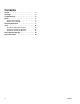
Contents Models . . . . . . . . . . . . . . . . . . . . . . . . . . . . . . . . . . . 3 Warnings . . . . . . . . . . . . . . . . . . . . . . . . . . . . . . . . . 4 Troubleshooting . . . . . . . . . . . . . . . . . . . . . . . . . . . . 5 Repair . . . . . . . . . . . . . . . . . . . . . . . . . . . . . . . . . . . . 6 Replace Power Supply . . . . . . . . . . . . . . . . . . . . 6 Replace Circuit Breaker . . . . . . . . . . . . . . . . . . . 6 Electrical Schematics . . . . . . . . . . . . . . . . . . . . . .
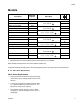
Models Models Description Maximum Amperes Description HFR Power Distribution Modules 230V, 1 Phase, Basic 55 A 230V, 1 Phase, Fully Loaded 116 A 230V, 3 Phase, Basic 29 A 230V, 3 Phase, Fully Loaded 73 A 400V, 3 Phase, Basic 55 A 400V, 3 Phase, Fully Loaded 63 A 200-240VAC, 1 phase, 50/60 Hz 2 wire and PE 200-240VAC, 3 phase Δ, 50/60 Hz 3 wire and PE 380-415VAC, 3 phase Y, 50/60 Hz 3 wire, neutral, and PE VRM Power Distribution Modules 230V, 3 Phase, Basic 60 A 230V, 3 Phase, Ful
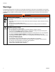
Warnings Warnings The following warnings are for the setup, use, grounding, maintenance, and repair of this equipment. The exclamation point symbol alerts you to a general warning and the hazard symbol refers to procedure-specific risk. Refer back to these warnings. Additional, product-specific warnings may be found throughout the body of this manual where applicable. WARNING ELECTRIC SHOCK HAZARD This equipment must be grounded. Improper grounding, setup, or usage of the system can cause electric shock.
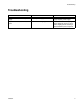
Troubleshooting Troubleshooting Problem Cause Solution No power received from DC power supply. Defective power supply. Check circuit breaker. Check power supply. Replace power supply. No power to MCM, heat zones, or tanks. Circuit breaker is tripping. Check circuit breaker for tripping and defects. Diagnose cause of circuit breaker tripping before resetting it. Replace defective parts if required.
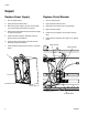
Repair Repair Replace Power Supply Replace Circuit Breaker 1. Turn off system power. 1. Turn off system power. 2. Open electrical enclosure door. 2. Open electrical enclosure door. 3. Disconnect power supply (1a) wires from the filter (1c) and the electrical enclosure connector. 3. Disconnect wire harness from circuit breaker. 4. Remove circuit breaker. 4. Remove nuts and washers that secure power supply to electrical enclosure. 5. Install new power supply to electrical enclosure.
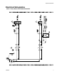
Electrical Schematics Electrical Schematics 230V, 1 Phase, Basic HFR Module Schematic 3A0239F 7
Electrical Schematics 230V, 1 Phase, Loaded HFR Module Schematic 8 3A0239F
Electrical Schematics 230V, 3 Phase, Basic HFR Module Schematic 3A0239F 9
Electrical Schematics 230V, 3 Phase, Basic VRM Module Schematic 10 3A0239F
Electrical Schematics 230V, 3 Phase, Loaded HFR Module Schematic 3A0239F 11
Electrical Schematics 230V, 3 Phase, Loaded VRM Module Schematic 12 3A0239F
Electrical Schematics 400V, 3 Phase, Basic HFR Module Schematic 3A0239F 13
Electrical Schematics 400V, 3 Phase, Basic VRM Module Schematic 14 3A0239F
Electrical Schematics 400V, 3 Phase, Loaded HFR Module Schematic 3A0239F 15
Electrical Schematics 400V, 3 Phase, Loaded VRM Module Schematic 16 3A0239F
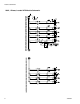
Electrical Schematics 230V, 3 Phase, Loaded VPM Module Schematic 3A0239F GND 1L3 1 HARNESS 1L1 1L2 1L3 PG105 GND L3 L2 1L1 DISC-1 1 GND 1L1 1080 BLK 1080 1L2 1100 RED 1100 WHT 1120 1L3 1120 CB1 30A L1 331 L2 PG116 1L2 1L2 1L3 1L3 1160 1160 1180 1180 CB2 20A 1L3 1L3 PRIMARY HT B VOLUME HARNESS 1220 1220 1240 1240 1 GND 1L1 1 511 PG121 1L1 MCM B VOLUME L3 HARNESS CB3 15A TANK VOLUME HARNESS PG133 1L2 1L1 1340 1L2 1360 1340 1360 1340 MISC B VOLUME 13
Electrical Schematics 400V, 3 Phase, Loaded, Non-CE, VPM Module Schematic 18 GND 1N 1L3 1 HARNESS 1L1 1N PG105 GND N L3 GND 1L1 1080 BLK 1080 1N 1100 WHT 1100 CB1A 63A L1 331 L2 PG116 1L2 1L2 1N 1N 1160 1160 1180 1180 CB2 20A 1N 1N PRIMARY HT B VOLUME HARNESS 1220 1220 1240 1240 1 GND 1L2 1 511 PG121 1L2 MCM B VOLUME L3 HARNESS CB3 15A TANK B VOLUME HARNESS PG133 1L2 1N 1L2 1340 1N 1360 1340 1360 1340 MISC B VOLUME 1390 BR L1/P 1400 BL L2/N LINE 1 75
Electrical Schematics 400V, 3 Phase, Loaded, CE approved, VPM Module Schematic 3A0239F GND 1N HARNESS POWER FILTER 1L1 1N 1L1 1081 1N 1101 L2/N LINE CB1A 63A L1/P BLK 1080 1100 WHT 1100 1L2 1N 1N L1 331 L2 PG116 1160 1160 1180 1180 CB2 20A 1N 1N PRIMARY HT B VOLUME HARNESS 1220 1220 1240 1240 1 GND 1L2 1 511 PG121 1L2 MCM B VOLUME L3 HARNESS GND 1L2 GND 1080 LOAD 1L3 1 PG105 GND N L3 CB3 15A TANK B VOLUME HARNESS PG133 1N 1340 1N 1360 1340 1340 1360
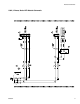
Parts Parts HFR Power Distribution Modules 400V, 3 Phase, Basic Module Shown 19 56 62 18, 48 56 4 9 5, 6 1 3 14 69 2 8 23 7 21 8 r_24C686_3A0239_2b 3 13 39 12 11 10 35 46 8 46 44 Circuit Breaker Detail for 400V, 3 Phase, Loaded Module 10 7 11 r_24C688_3A0239_4a 39 20 35 36 38 36 35 3A0239F
Parts 1c 24 26 61 26 27 20 1a 27 r_24C680_3A0239_5a Parts Used on All HFR Modules Ref. 1 1a Part Description Qty. --ENCLOSURE 1 24D207 SUPPLY, power; 24 Vdc, 4A, 1 100W, 230 Vac 1b 196548 LABEL, caution 1 (on enclosure door) 1c 123718 FILTER 1 2 --PANEL, electrical 1 3 123396 NUT, flange, serrated; 3/8-16 4 4 117666 TERMINAL, ground 1 5 113783 SCREW, mach, pan hd 1 6 100985 WASHER, lock ext 1 7 16A647 RAIL, din, 17.7 in.
Parts Parts that Vary by HFR Module Use the following table to locate parts that vary by module. See Parts Used on All HFR Modules, page 21, for parts used on all HFR modules. Ref.
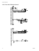
Parts VRM Power Distribution Modules 400V, 3 Phase, Basic Module Shown 19 57 56 55 18, 48 8, 49, 50 23 4 5, 6 2 56 3 14 69 1 21 23 7 21 8 3 13 12 39 35 11 10 8 9 r_24C687_3A0239_3a 46 Circuit Breaker Detail for 400V, 3 Phase, Loaded Module 46 44 10 7 11 39 3A0239F 35 36 38 36 35 39 r_24C689_3A0239_7a 23
Parts 63, 64, 65 24 26 1c 20 20 1a 27 28 27 26 25 29 Parts Used on All VRM Modules Ref. 1 1a Part Description Qty. --ENCLOSURE 1 24D207 SUPPLY, power; 24 Vdc, 4A, 1 100W, 230 Vac 1b 196548 LABEL, caution 1 (on enclosure door) 1c 123718 FILTER 1 2 --PANEL, electrical 1 3 123396 NUT, flange, serrated; 3/8-16 4 4 117666 TERMINAL, ground 1 5 113783 SCREW, mach, pan hd 1 6 100985 WASHER, lock ext 1 7 16A647 RAIL, din, 17.7 in.
Parts Parts that Vary by VRM Module Use the following table to locate parts that vary by module. See Parts Used on All VRM Modules, page 24, for parts used on all VRM modules.
Parts VPM Power Distribution Modules 400V, 3 Phase, Basic Module Shown 1 23 18, 48 19 57 55 49, 50, 8 23 2 62 14 3 69 8 21 5, 6 4 13 9 57 8 3 ti18046a 7 12 46 Circuit Breaker Detail for 400V, 3 Phase, Loaded Module 44 39 8 35 36 37 35 39 10, 47 7 ti18047a 26 3A0239F
Parts 25 26 1c 61 1b 1a 70 20 24 70 71 28 27 29 3A0239F ti18048a 71 27
Parts Parts Used on All VPM Modules Ref. 1 1a Part Description --ENCLOSURE 24D207 SUPPLY, power; 24Vdc, 4A, 100W, 230 Vac 1b 196548 LABEL, caution (on enclosure door) 1c 123718 FILTER 2 16A360 PANEL, electrical 3 123396 NUT, flange, serrated; 3/8-16 4 117666 TERMINAL, ground 5 113783 SCREW, mach, pan hd 6 100985 WASHER, lock ext 7 16A647 RAIL, din, 17.7 in.
Parts 3A0239F 29
Graco Standard Warranty Graco Standard Warranty Graco warrants all equipment referenced in this document which is manufactured by Graco and bearing its name to be free from defects in material and workmanship on the date of sale to the original purchaser for use. With the exception of any special, extended, or limited warranty published by Graco, Graco will, for a period of twelve months from the date of sale, repair or replace any part of the equipment determined by Graco to be defective.