Setup - Operation 1053/1093 3A0261H EN Control Box Patented meter and dispense system for precise one-component micro-dispensing. Not for use in explosive atmospheres. Important Safety Instructions Read all warnings and instructions in this manual. Save these instructions.
Contents Related Manuals . . . . . . . . . . . . . . . . . . . . . . . . . . . 3 Warnings . . . . . . . . . . . . . . . . . . . . . . . . . . . . . . . . . 4 Component Identification . . . . . . . . . . . . . . . . . . . . 6 Control Boxes . . . . . . . . . . . . . . . . . . . . . . . . . . . 6 Grounding . . . . . . . . . . . . . . . . . . . . . . . . . . . . . . . . 7 Kits . . . . . . . . . . . . . . . . . . . . . . . . . . . . . . . . . . . . . . 7 Valve Connection Kits . . . . . . . . . . . . . . . . . .
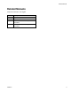
Related Manuals Related Manuals Component manuals in U.S. English.
Warnings Warnings The following warnings are for the setup, use, grounding, maintenance, and repair of this equipment. The exclamation point symbol alerts you to a general warning and the hazard symbol refers to procedure-specific risk. Refer back to these warnings. Additional, product-specific warnings may be found throughout the body of this manual where applicable.
Warnings WARNING PRESSURIZED EQUIPMENT HAZARD Fluid from the gun/dispense valve, leaks, or ruptured components can splash in the eyes or on skin and cause serious injury. • Follow Pressure Relief Procedure in this manual, when you stop spraying and before cleaning, checking, or servicing equipment. • Tighten all fluid connections before operating the equipment. • Check hoses, tubes, and couplings daily. Replace worn or damaged parts immediately.
Component Identification Component Identification Control Boxes B A C CONTROL POWER D AUDIO ALARM START OPTIONS 4 1 3 2 MOTOR VALVE I/O F VERIFY INCOMING VOLTAGE WITH VOLTAGE SWITCH SETTING BEFORE CONNECTING POWER L U E J H Key: A B C D E Emergency Stop Control Power Switch Touch Panel Alarm Speaker Power Input F H J L U Start Options Connection A Tank Level Controls Connection B Tank Level Controls Connection Dispense Valve I/O Connection Motor Connection FIG.
Grounding Grounding Kits NOTE: 80/2957-1/50 1053/1093 control requires three sensor switches to operate. Valve, control, and connection kits are sold separately. Some assembly required. This product must be grounded. In the event of an electrical short circuit, grounding reduces the risk of electric shock by providing an escape wire for the electric current. Grounding plug units: this product is equipped with a cord having a grounding wire with an appropriate grounding plug.
Valve Connection Kits Valve Connection Kits These valve connection kits enable certain valves to be used with this control package. Each kit contains the mechanical, electrical, and pneumatic hardware needed to install the valve. See associated drawing for hardware location and wiring information. 24E845, 1053 Dispense Valve with Added Up and Down Validation/Actuation Kit NOTE: PX-HOME must be below PX-UP. PX-HOME may have been supplied in top hole. If so move to the appropriate location as shown.
Valve Connection Kits Ref 1 2 3 4 5 6 14 15 16 17 18 19 20 21 22 23 24 25 26 27 28 Part 96/0098/99 16C798 ADM00022 81/0360-N/11 B2050001 297331 81/1265/11 297639 81/0283-DIN/11 F0200075 81/0378-2/25 100166 96/0005-2/99 84/0130-25/11 16D050 94/0740-A/99 127629 82/0217-A/11 127632 94/0705-1/96 17A412 Description SCREW, socket head, 10-24x1.
Valve Connection Kits 24E846, 1053 Dispense Valve with Added Up Validation/Actuation Kit NOTE: PX-HOME must be below PX-UP. PX-HOME may have been supplied in top hole. If so move to the appropriate location as shown.
Valve Connection Kits Ref 1 2 3 4 5 6 14 15 16 17 18 19 20 21 22 23 24 25 26 27 28 Part 96/0098/99 16C798 ADM00022 81/0360-N/11 B2050001 297331 81/1265/11 297639 81/0283-DIN/11 F0200075 81/0378-2/25 100166 96/0005-2/99 84/0130-25/11 16D050 94/0740-A/99 127629 82/0217-A/11 127632 94/0705-1/96 17A412 Description SCREW, socket head, 10-24x1.
Valve Connection Kits 24E847, 1093 Dispense Valve with Added Actuation Kit NOTE: PX-HOME must be below PX-UP. PX-HOME may have been supplied in top hole. If so move to the appropriate location as shown.
Valve Connection Kits Ref 3 4 5 6 18 19 20 21 24 25 26 27 28 Part ADM00022 81/0360-N/11 B2050001 297331 81/0378-2/25 100166 96/0005-2/99 84/0130-25/11 127629 82/0217-A/11 127632 94/0705-1/96 17A412 Description COVER, connector, dsub, 15p, 45deg SCREW, jack, connector, dsub, type a NUT, allen, 4-40, alloy SCREW, cap, 4x1/4 STRAP, ground, ring, #10, 16ga NUT, full hex WASHER, lock, ext, #10 LABEL, prot earth(grnd).375x.
Setup Setup Adjust Amplifier The amplifier should be adjusted if: Motor Driven • • 1. Connect Dispense Valve I/O, Start Options, and Motor logic cables. If level controls are installed, connect Level Controls logic cables. NOTICE Feed system and main logic control system must use separate air supplies. Debris or vibration changed the distance/axis between the sensor and metering block (13). Replacing the sensor. 1. Navigate to the Motor Status screen. 2.
Startup Startup Dispensing Operation NOTE: See HMI Operation starting on page 16 for detailed HMI instructions. NOTE: See HMI Operation on page 16 for detailed HMI instructions. 1. Press the Control Power On button. The foot switch, the “Start” button, and the optional Customer Start Signal can be used to initiate shots. These are referred to as start devices. 2. Navigate to the Metering Valve Control screen. 3. Press the Retract button.
HMI Operation HMI Operation Screen Navigation Diagrams Motor Driven Main Screen Metering Valve Control Shot Size/Flow Rate Level 1 Control Level 2 Control Purge Timer Status Supervisor Motor Status Motor Error Codes Supervisor Help FIG.
HMI Operation Main Screen NOTE: The Error Code button is shown on every screen on the Motor Driven model. Screen Access Buttons All buttons on the main screen except for the Password and Error Code buttons open a new specified screen. For example, pressing the “Status” button opens the Status screen. Password The password button enables the user to changes values in certain screens. To access the password press the Password Access button (shown as “=0000”).
HMI Operation Metering Valve Control Screen NOTE: A “1” indicates that the button is in the “ON” position. A “0” indicates that the button is in the “OFF” position. NOTE: The Error Code button is shown on every screen. See the Main screen for definition. Start button Extend Mode When the Start button is pressed, the machine starts the cycle for the selected Pump Mode. The air cylinder and pumps immediately extend and remain in the extended position.
HMI Operation DV Valve Mode This mode actuates an optional dispense valve. OPEN In this mode, the dispense valve is held in the open position, allowing material to pass through. AUTO In this mode, the dispense valve opens automatically whenever the pump is cycled. CLOSE In this mode, the dispense valve is held closed.
HMI Operation Shot Size Screen NOTICE Erratic operation results if the shot size value entered is not greater than the absolute value of the Shot Size Offset setting. For example, if the Shot Size Offset setting is -1%, a shot size greater than 1% must be entered. See Supervisor screen, page 28. Select Shot Size/Flow Rate Combination Use this to change the selected shot by entering a number between 1 and 7.
HMI Operation Level 1 Control Screen NOTE: The Error Code button is shown on every screen. See the Main screen for definition, page 17. NOTE: If ‘A Tank Status’ and ‘B Tank Status’ both display 'Levels Not Active' then the level control feature is not installed on this machine. A Tank Status, B Tank Status Start Fill A, Start Fill B button This displays information about each component tank filling process. The following are the possible messages.
HMI Operation Level 2 Control Screen NOTE: A “1” indicates that the button is in the “ON” position. A “0” indicates that the button is in the “OFF” position. NOTE: The Error Code button is shown on every screen on the Motor Driven PD44. See the Main screen for definition, page 17. NOTE: In the Level 1 Control Screen, if ‘A Tank Status’ and ‘B Tank Status’ both display 'Levels Not Active' then the level control feature is not installed on this machine. Press the Main button to exit from this screen.
HMI Operation Shutdown Timer button/indicator NOTE: If the level control option has not been purchased the Shutdown Timer button is disabled. This changes the delay before the Fill Timer Fault message is displayed in the corresponding ‘A Tank Status’ or ‘B Tank Status’ field on the Level 1 Control screen. If the material level is below the low level sensor for more than the duration of the Shutdown Timer setting, the machine shuts down. NOTE: For example, if 15 is entered, the Fill Timer setting is 1.
HMI Operation Purge Timer Screen NOTE: The Error Code button is shown on every screen. See the Main screen for definition, page 17. Purge Timer On /Off Always set the dwell/alarm timer to a value that will give the user adequate warning that the machine is about to dispense a purge shot.See Dwell / Alarm Timer section on page 25. The Purge Timer On/Off switch is used to enable/disable the Purge Timer. Enter Purge Time Button The Enter Purge Time button is shown as “=000.
HMI Operation NOTE: The current Purge Timer time is shown in the bottom text box below the Purge Timer button. 1. Select Purge Shot Size % button. A numeric keypad appears. Calculating the Purge Timer Setting 2. Enter the desired material shot size volume. If the shot size is larger than the mixer volume, set the timer for one-half the gel time of the material. If the shot size is smaller, use the following formula to determine the Purge Timer setting. 3. Press the button.
HMI Operation Status Screen NOTE: A “1” indicates that the button is in the “ON” position. A “0” indicates that the button is in the “OFF” position. NOTE: The Error Code button is shown on every screen. See the Main screen for definition, page 17. Maintenance Totalizer Dispense Complete This counter increments each time the machine cycles. Press the Reset Maintenance Totalizer button to reset. This counter is used for maintenance purposes.
HMI Operation Motor Status Screen NOTE: A “1” indicates that the button is in the “ON” position. A “0” indicates that the button is in the “OFF” position. NOTE: The Error Code button is shown on every screen. See the Main screen for definition, page 17. To navigate to the Motor Status screen, press the “Motor Status” button on the Status screen. Motor Position (Steps) CSV Switch (Closed Spool Valve Switch) This displays “1” when the spool valve is in the closed or reload position.
HMI Operation Supervisor Screen NOTE: A “1” indicates that the button is in the “ON” position. A “0” indicates that the button is in the “OFF” position. NOTE: To change the values on this screen, log-in as the supervisor. See Main Screen, page 17. Error Code button This button resets the error in the error string (shown as “<0000000000”) and the error code number (shown as “<000”). See the Motor Error Code screen for more information, page 31.
HMI Operation Valve Type Only one of the three valve type options can be enabled at any given time. This feature is enabled at the time of build based on Valve Type and should not be manipulated. Enabling the Valve Type with a 1053 - 1 in. when a 1053 - 2 in. or 1093 is used will cause the improper maximum shot size allowed by the mechanics of the valve. Enabling the Valve Type with the 1053 - 2 in. when a 1053 - 1 in. will cause the Low Switch to be tripped and will not allow the Valve to cycle.
HMI Operation Supervisor Help Screen This screen describes the various reload and shot options in the Supervisor screen. To get to the Setup Help screen, press the “Help” button on the Supervisor screen.
HMI Operation Motor Error Codes Screen These screens give descriptions of the motor error codes.
Pressure Relief Procedure Pressure Relief Procedure Shutdown 1. Go to the Metering Valve Control screen. 1. Turn main air supply shut-off/bleed valve to the off position. This will bleed air from the system. 2. Perform feed system pressure relief procedure. See Related Manuals on page 3. 3. Perform dispense valve pressure relief procedure. See Related Manuals on page 3. 2. Press the Retract button. 3. Press the Extend button. 4. Press the Emergency Stop button. Ensure everything is off. 5.
Customer Inputs Customer Inputs Name Description Customer Start (Input) When a momentary contact closure is applied to this input, the start device is activated. When a momentary contact closure is applied to this input, the purge shot is activated. When these inputs are activated in the proper sequence, the machine activates the Shot Size and Flow Rate Combination seen on the Shot Sizes screen. See the machine logic drawings for more information.
Maintenance Maintenance NOTE: If material is leaking, see Troubleshooting on page 34. See Related Manuals on page 3 for dispense valve and feed system maintenance socket schedule and procedures. Air-Water Separator/Filter Drain water once a shift or as necessary. Troubleshooting Perform Pressure Relief Procedure before performing any troubleshooting procedure.
310 1L1 2L1 2L1 9 4 8 3 7 PORT-1 14 AWG L+ EXP-1 2 6 1 22 AWG G G 9 4 8 3 7 2 M PORT-0 5 6 1 6 W N 2L2 PROGRAMMING 6 349 22 AWG EEPROM A2 6 6 6 6 22 AWG 22 AWG CRM PL-1 A1 PROGRAMMING BATTERY 6 6 2L2 369 368 367 366 365 364 363 362 361 360 359 358 357 356 355 354 353 352 351 350 2L2 DC COM 6 348 347 349 1L2 372 24VDC 5 8 8 M CONTROL POWER 22 AWG 24V DC NOTE: SET SWITCHES FOR DP/MPI 6 XO 12 22 AWG PB-2 L+ N(L2) BLK
380 24VDC 1 8 PG-2 BRN BRN DISPENSE PX-OSV RELOAD PX-CSV PG-1 4 9 10 C PG-2 WHT PG-2 WHT 22 AWG ORG/BLK BLU/BLK WHT 32 31 30 29 I0.3 I0.2 I0.1 I0.0 6 6 NONE SPOOL DISPENSE POSITION SPOOL RELOAD POSITION START SIGNAL 429 428 427 426 425 424 423 422 421 BRN BRN BRN PX- PX- PX- BLK BLU BLK BLU BLK BLU BLK BLU PR C PR C PR C PR PR BLK BLK 22 AWG C PR BLK 22 AWG C PR BLK 22 AWG C PR C WHT WHT WHT 39 38 33 I1.2 I1.1 I1.
572 571 570 569 568 567 566 565 564 563 562 561 560 559 558 557 556 555 554 ENCLOSURE GROUND STUD SEE NOTE 1 PE INCOMING GROUND PROTECTIVE EARTH MIN 14 AWG GRN/YEL PE GROUND STUD GRN/YEL (14 AWG) 553 STAR WASHER STAR WASHER NTS FIGURE 1 GROUND DIST.
Schematics 38 3A0261H
Technical Data Technical Data Maximum Ambient Temperature. . . . . . . . . . . . . . . . . . . . Maximum Operating Temp . . . . . . . . . . . . . . . . . . . . . . . . Electrical Requirements . . . . . . . . . . . . . . . . . . . . . . . . . . Fuses Required . . . . . . . . . . . . . . . . . . . . . . . . . . . . . . . . 110°F (43°C) 150°F (65°C) 120/240V, 50/60 Hz 5 x 20 mm, 10A, fast, type F, 250 VAC (Graco part V-21610P, Qty = 2) Maximum Amperage . . . . . . . . . . . . . . . . . . . . . . . . . . . .
Graco Standard Warranty Graco warrants all equipment referenced in this document which is manufactured by Graco and bearing its name to be free from defects in material and workmanship on the date of sale to the original purchaser for use. With the exception of any special, extended, or limited warranty published by Graco, Graco will, for a period of twelve months from the date of sale, repair or replace any part of the equipment determined by Graco to be defective.